Absolute maximum ratings, Recommended dc operating conditions, Dc electrical characteristics – Rainbow Electronics DS2712 User Manual
Page 2: 0v £ v, 5v; t, 20 °c to +70°c.), 5v, t
DS2711/DS2712: Loose Cell NiMH Charger
2 of 13
ABSOLUTE MAXIMUM RATINGS*
Voltage on All Pins Relative to V
SS
-0.3V to +6V
Voltage on DMSEL
V
DD
+ 0.3V
Continuous Sink Current CC1, CC2, LED1, LED2 and CSOUT
20mA
Operating Temperature Range
-40°C to +85°C
Storage Temperature Range
-55°C to +125°C
Soldering Temperature
See IPC/JEDECJ-STD-020
*This is a stress rating only and functional operation of the device at these or any other conditions above those
indicated in the operation sections of this specification is not implied. Exposure to absolute maximum rating
conditions for extended periods of time may affect reliability.
RECOMMENDED DC OPERATING CONDITIONS
(4.0V
£ V
DD
£ 5.5V; T
A
= -20
°C to +70°C.)
PARAMETER SYMBOL CONDITIONS MIN
TYP
MAX
UNITS
Supply Voltage
V
DD
(Note
1)
4.0
5.5
V
Input Voltage Range
LED2, DMSEL
-0.3
+5.5
V
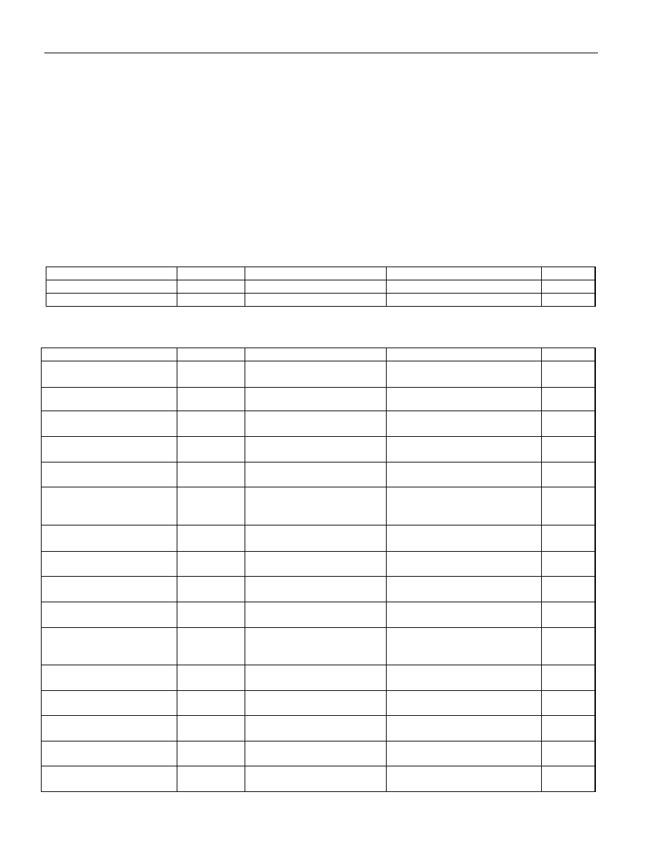
DC ELECTRICAL CHARACTERISTICS
(4.0V
£ V
DD
£ 5.5V, T
A
= -20
°C to +70°C, unless otherwise noted.)
PARAMETER SYMBOL CONDITIONS MIN
TYP
MAX
UNITS
Supply Current, V
DD
I
DD
Operating
mode
250 500 mA
UVLO Threshold
V
UVLO
V
DD
rising (Note 1)
3.5
3.9
V
UVLO Hysteresis
V
UHYS
V
DD
falling from above
V
UVLO
40 mV
Output-Voltage Low,
CC1, CC2, LED1, LED2
V
OL1
V
DD
= 5.0V,
I
OL
= 20mA (Note 1)
1.0
V
Output-Voltage Low,
CSOUT
V
OL2
V
DD
= 5.0V,
I
OL
= 20mA (Note 1)
0.75
1.25 V
Leakage Current,
CC1, CC2, LED1, LED2,
CSOUT
I
LKG
V
DD
= 5.0V,
Output inactive
-1 +1
mA
Threshold Voltage,
-
DV Termination
V
-
DV
After t
THO
1.0 2.0 3.0 mV
Mode Test Current,
DMSEL, LED2
I
MTST
(Notes
2,
3)
5
15 mA
Input Logic-High,
DMSEL, LED2
V
IH
(Note
1)
V
DD
-
0.2V
V
Input Logic-Low, DMSEL,
LED2
V
IL
(Note
1)
0.2 V
Input Leakage Current,
DMSEL
I
IL1
After power-up mode
select,
DMSEL = V
DD
or V
SS
-1 +1
mA
Threshold Voltage, Cell
Test
V
CTST
R
CTST
= 80k
W
85 100 115 mV
Threshold Voltage, Cell
Voltage Low
V
BAT-LOW
CC1 = CC2 = high-Z
(Note 4)
0.9 1.0 1.1 V
Threshold Voltage, Cell
Voltage Max1
V
BAT-MAX1
CC1 = CC2 = high-Z
(Note 4)
1.55 1.65 1.75 V
Threshold Voltage, Cell
Voltage Max2
V
BAT-MAX2
CC1, CC2 active
(Note 4)
1.64 1.75 1.86 V
Threshold Voltage Delta
V
BAT-MAX∆
V
BAT-MAX2
- V
BAT-MAX1
(Note 5)
90 100 110 mV