Ds4426 quad-channel, i, Applications information – Rainbow Electronics DS4426 User Manual
Page 13
Applications Information
Example Calculations for an Adjustable
Power Supply
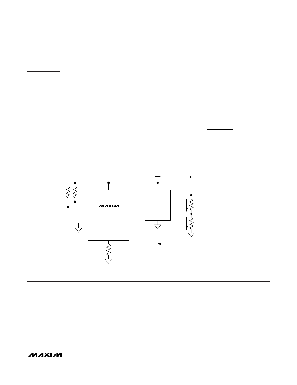
In this example, the circuit shown in Figure 8 is used to
margin a +2.0V supply by ±20%. The margined power
supply has a DC-DC converter output voltage, V
OUT
, of
+2.0V and a DC-DC converter feedback voltage, V
FB
,
of +0.8V. To determine the relationship of R
0A
and R
0B
,
start with the equation:
Substituting V
FB
= +0.8V and V
OUT
= +2.0V, the rela-
tionship between R
0A
and R
0B
is determined to be:
R
0A
= 1.5 x R
0B
I
OUT0
is chosen to be 100µA (midrange source/sink
current for the DS4426). Summing the currents into the
feedback node, we have the following:
I
OUT0
= I
R0B
- I
R0A
where:
and
To create a ±20% margin in the supply voltage, the
value of V
OUT
is set to +2.4V. With these values in
place, R
0B
is calculated to be 2.67k
Ω, and R
0A
is
I
V
V
R
R A
OUT
FB
A
0
0
=
−
I
V
R
R B
FB
B
0
0
=
V
R
R
R
V
FB
B
A
B
OUT
=
+
×
0
0
0
DS4426
Quad-Channel, I
2
C-Margining IDACs with
Three Channels of Power-Supply Tracking
______________________________________________________________________________________
13
DC-DC
CONVERTER
FB
OUT
SDA
SCL
OUT0
GND
R
FS0
= 80k
Ω
4.7k
Ω
4.7k
Ω
V
CC
V
CC
V
OUT
= 2.0V*
FS0
R
0B
= 2.67k
Ω
R
0A
= 4k
Ω
V
FB
= 0.8V*
I
R0A
I
R0B
I
OUT0
DS4426
*V
OUT
AND V
FB
VALUES ARE DETERMINED BY THE DC-DC CONVERTER AND SHOULD NOT BE CONFUSED WITH V
OUT
AND V
REF
OF THE DS4426.
Figure 8. Example Typical Application Circuit