Ds4426 quad-channel, i, C slave address, Table 1. slave addresses – Rainbow Electronics DS4426 User Manual
Page 10
Inputs for Tracking in DC-DC Power
Applications
When enabling/disabling the power-supply tracking, a
resistor-divider connected to the THR input sets the dis-
able threshold (see V
THRESHOLD
in Figure 4). The top
of the resistor-divider must be connected to the master
DC-DC voltage for correct operation. Below this thresh-
old, the tracking circuit is active.
Power-Supply Sequencing
The DS4426 can be used to perform power-supply
sequencing. This is a subset of power-supply tracking
with modifications to the external resistor network. The
basic concept is that the DS4426 sources maximum
current into the slave power supply's feedback node
until a voltage in the system has risen above a specific
voltage level. By sourcing the maximum current into the
feedback node, the power supply's output is held off.
Maximum sourcing current is achieved with two steps:
1) Apply the maximum allowed input voltage across
INP and INN. Connect INP to V
CC
- 1.4V using a
voltage-divider to ground. Connect INN to ground.
2) Set the gain to the maximum allowed (R
L
/R
G
= 5).
The slave power supply is allowed to turn on once the
voltage on THR is greater than V
REF
/2. Use a resistor-
divider connected to the rising system voltage to scale
the trip point to V
REF
/2.
I
2
C Slave Address
The DS4426 responds to one of four I
2
C slave address-
es determined by the state of the input on the two
address inputs. The two input states are connected to
V
CC
or connected to ground.
Memory Organization
The DS4426’s current sources are controlled by writing
to memory addresses listed in Table 2.
The format of each of the output control registers is
given by:
where:
For example:
R
FS0
= 80k
Ω and register 0xF8h is written to a value of
0xAAh. Use the following formula to calculate the out-
put current:
I
FS
= (1.0V/80k
Ω) x (127/16) = 99.22µA
The MSB of the output register is 1, so the output is
sourcing the value corresponding to position 2Ah (42
decimal). The magnitude of the output current is equal
to the following:
99.22µA x (42/127) = 32.8125µA
DS4426
Quad-Channel, I
2
C-Margining IDACs with
Three Channels of Power-Supply Tracking
10
______________________________________________________________________________________
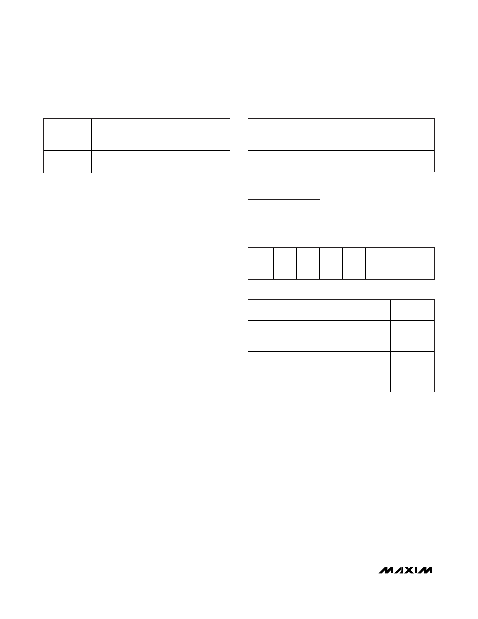
A1
A0
SLAVE ADDRESS (HEX)
GND GND
90h
GND V
CC
92h
V
CC
GND
94h
V
CC
V
CC
96h
Table 1. Slave Addresses
MEMORY ADDRESS (HEX)
CURRENT SOURCE
F8h OUT0
F9h OUT1
FAh OUT2
FBh OUT3
Table 2. Memory Addresses
BIT 7
(MSB)
BIT 6 BIT 5 BIT 4 BIT 3 BIT 2 BIT 1
BIT 0
(LSB)
S D
6
D
5
D
4
D
3
D
2
D
1
D
0
BIT
NAME
DESCRIPTION
POWER-ON
DEFAULT
S
Sign
Bit
Determines if DAC sources or
sinks current. For sink, S = 0.
For source, S = 1.
0b
D
X
Data
7-bit data word controlling DAC
output. Setting 0000000b
outputs zero current regardless
of the state of the sign bit.
0000000b