Rainbow Electronics ADC1175 User Manual
General description, Features, Key specifications
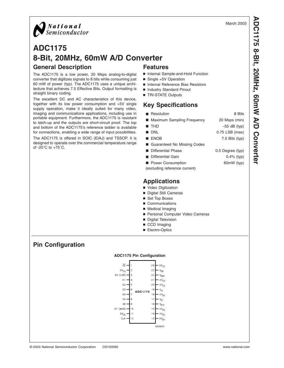
Table of contents
Document Outline
- ADC1175
- General Description
- Features
- Key Specifications
- Applications
- Pin Configuration
- Ordering Information
- Block Diagram
- Pin Descriptions and Equivalent Circuits
- Absolute Maximum Ratings
- Operating Ratings(Notes , )
- Converter Electrical Characteristics
- Typical Performance Characteristics
- Specification Definitions
- Timing Diagram
- FIGURE 2. tEN, tDISTest Circuit
- Functional Description
- Applications Information
- 1.0 THE ANALOG INPUT
- 2.0 REFERENCE INPUTS
- FIGURE 3. Simple, Low Component Count, Self -Bias Reference application. Because of resistor toleran
- FIGURE 4. Better defining the ADC Reference Voltage. Self-bias is still used, but the reference volt
- FIGURE 5. Driving the reference to force desired values requires driving with a low impedance source
- 3.0 POWER SUPPLY CONSIDERATIONS
- 4.0 THE ADC1175 CLOCK
- 5.0 LAYOUT AND GROUNDING
- FIGURE 6. Layout example showing separate analog and digital ground planes connected below the ADC11
- 6.0 DYNAMIC PERFORMANCE
- FIGURE 7. Isolating the ADC clock from Digital Circuitry.
- 7.0 COMMON APPLICATION PITFALLS
- FIGURE 8. 5.5 MHz Low Pass Filter to Eliminate Harmonics at the Signal Input.
- FIGURE 9. 11 MHz Low Pass filter to eliminate harmonics at the signal input. Use at input frequencie
- Physical Dimensions