Wire interface, Figure 9. 3-wire single byte transfer – Rainbow Electronics DS1306 User Manual
Page 14
DS1306
14 of 21
3-WIRE INTERFACE
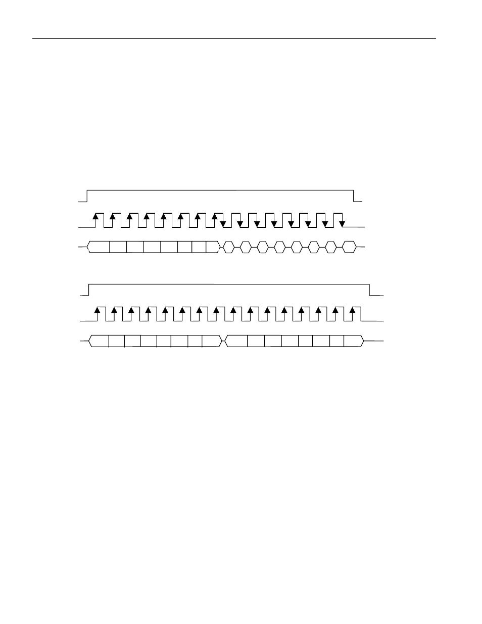
The 3-wire interface mode operates similar to the SPI mode. However, in 3-wire mode there is one I/O
instead of separate data in and data out signals. The 3-wire interface consists of the I/O (SDI and SDO
pins tied together), CE, and SCLK pins. In 3-wire mode, each byte is shifted in LSB first, unlike SPI
mode, where each byte is shifted in MSB first.
As is the case with the SPI mode, an address byte is written to the device followed by a single data byte
or multiple data bytes. Figure 9 illustrates a read and write cycle. In 3-wire mode, data is input on the
rising edge of SCLK and output on the falling edge of SCLK.
Figure 9. 3-WIRE SINGLE BYTE TRANSFER
Single-Byte Read
Single-Byte Write
In burst mode, CE is kept high and additional SCLK cycles are sent until the end of the burst.
*I/O is SDI and SDO tied together.
A0 A1 A2
A3 A4
A5 A6
1
CE
SCLK
I/O*
D0
D1
D2
D3
D4 D5 D6 D7
D0 D1 D2 D3 D4 D5 D6 D7
A0 A1 A2 A3 A4 A5 A6 0
I/O*
CE
SCLK