Address map, Table 2. timekeeper registers – Rainbow Electronics DS1337 User Manual
Page 8
DS1337 I
2
C Serial Real-Time Clock
8 of 15
ADDRESS MAP
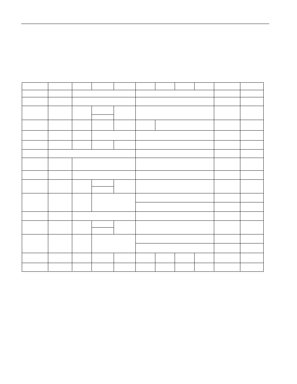
Table 2 shows the address map for the DS1337 registers. During a multibyte access, when the address pointer
reaches the end of the register space (0Fh) it wraps around to location 00h. On an I
2
C START, STOP, or address
pointer incrementing to location 00h, the current time is transferred to a second set of registers. The time
information is read from these secondary registers, while the clock may continue to run. This eliminates the need
to re-read the registers in case of an update of the main registers during a read.
Table 2. Timekeeper Registers
ADDRESS
BIT 7
BIT 6
BIT 5
BIT 4
BIT 3
BIT 2
BIT 1
BIT 0
FUNCTION
RANGE
00H 0
10
Seconds
Seconds
Seconds
00–59
01H 0
10
Minutes
Minutes
Minutes
00–59
AM/PM
02H 0
12/
24
10 Hour
10 Hour
Hour
Hours
1–12
+AM/PM
00–23
03H 0 0 0 0 0
Day
Day 1–7
04H 0 0 10
Date
Date
Date
01–31
05H Century 0 0 10
Month
Month
Month/
Century
01–12 +
Century
06H 10
Year
Year
Year
00–99
07H A1M1
10
Seconds
Seconds
Alarm 1
Seconds
00–59
08H A1M2
10
Minutes
Minutes
Alarm 1
Minutes
00–59
AM/PM
09H A1M3
12/
24
10 Hour
10 Hour
Hour
Alarm 1
Hours
1–12 +
AM/PM
00–23
Day
Alarm 1
Day
1–7
0AH A1M4
DY/
DT
10 Date
Date
Alarm 1
Date
1–31
0BH A2M2
10
Minutes
Minutes
Alarm 2
Minutes
00–59
AM/PM
0CH A2M3
12/
24
10 Hour
10 Hour
Hour
Alarm 2
Hours
1–12 +
AM/PM
00–23
Day
Alarm 2
Day
1–7
0DH A2M4
DY/
DT
10 Date
Date
Alarm 2
Date
1–31
0EH
EOSC
0 0 RS2
RS1
INTCN
A2IE
A1IE
Control —
0FH OSF 0 0 0 0 0
A2F
A1F
Status —
Note: Unless otherwise specified, the state of the registers is not defined when power is first applied or V
CC
falls below the V
OSC
.