Pin description, Timing diagram – Rainbow Electronics DS1337 User Manual
Page 5
DS1337 I
2
C Serial Real-Time Clock
5 of 15
PIN DESCRIPTION
PIN
8 16
NAME FUNCTION
1 — X1
2 — X2
Connections for a Standard 32.768kHz Quartz Crystal. The internal
oscillator circuitry is designed for operation with a crystal having a specified
load capacitance (C
L
) of 6pF. For more information about crystal selection
and crystal layout considerations, refer to Application Note 58: Crystal
Considerations with Dallas Real-Time Clocks. An external 32.768kHz
oscillator can also drive the DS1337. In this configuration, the X1 pin is
connected to the external oscillator signal and the X2 pin is floated.
3 14
INTA
Interrupt Output. When enabled,
INTA is asserted low when the
time/day/date matches the values set in the alarm registers. This pin is an
open-drain output and requires an external pullup resistor.
4
15
GND
DC power is provided to the device on these pins.
5 16 SDA
Serial Data Input/Output. SDA is the input/output pin for the I
2
C serial
interface. The SDA pin is open-drain output and requires an external pullup
resistor.
6 1 SCL
Serial Clock Input. SCL is used to synchronize data movement on the serial
interface.
7 2
SQW/
INTB
Square-Wave/Interrupt Output. Programmable square-wave or interrupt
output signal. It is an open-drain output and requires an external pullup
resistor.
8 3 V
CC
DC power is provided to the device on these pins.
— 4–13 N.C.
No Connect. These pins are not connected internally, but must be
grounded for proper operation.
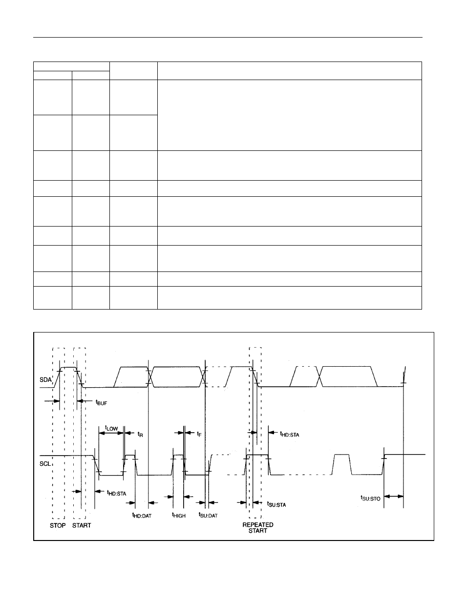
TIMING DIAGRAM