Rainbow Electronics HT49R70A-1 User Manual
Page 18
HT49R70A-1
Rev. 1.00
18
December 4, 2001
T E
S y s t e m C l o c k
T N 1
T N 0
T M R 1
T N 1
T N 0
T O N
P u l s e W
i d t h
M e a s u r e m e n t
M o d e C o n t r o l
1 6 - b i t T i m e r / E v e n t C o u n t e r
P r e l o a d R e g i s t e r
1 6 - b i t T i m e r / E v e n t C o u n t e r
( T M R 1 H / T M R 1 L )
D a t a B u s
R e l o a d
R O M
C o d e
O p t i o n
M
U
X
T N 2
f
S Y S
/ 4
T i m e B a s e O u t
T M R 0 O V
T
Q
P F D 1
P A 3 D a t a C T R L
O v e r f l o w
t o I n t e r r u p t
f
I N T
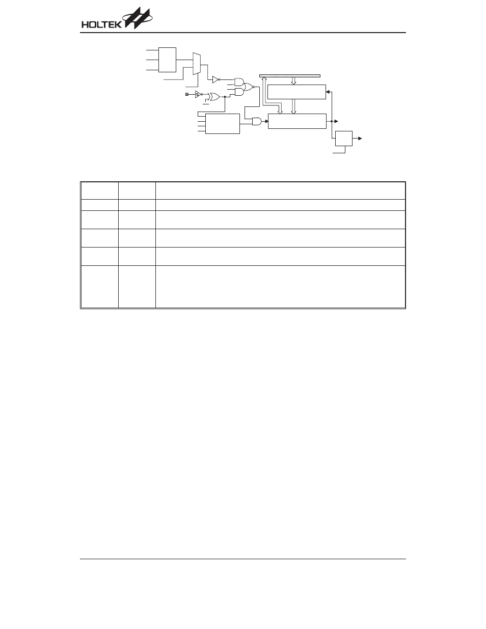
Timer/Event Counter 1
Label
(TMR1C)
Bits
Function
¾
0~2
Unused bit, read as
²0²
TE
3
Defines the TMR1 active edge of the timer/event counter
(0= active on low to high; 1= active on high to low)
TON
4
Enable/disable timer counting
(0= disabled; 1= enabled)
TN2
5
2 to 1 multiplexer control inputs to select the timer/event counter clock source
(0= option clock source; 1= system clock/4)
TN1
TN0
7
6
Defines the operating mode
01= Event count mode (External clock)
10= Timer mode (Internal clock)
11= Pulse Width measurement mode (External clock)
00= Unused
TMR1C register
When the timer/event counter (reading TMR0/TMR1) is
read, the clock is blocked to avoid errors, as this may re-
sults in a counting error. Blocking of the clock should be
taken into account by the programmer.
It is strongly recommended to load a desired value into
the TMR0/TMR1 register first, before turning on the re-
lated timer/event counter, for proper operation since the
initial value of TMR0/TMR1 is unknown.
Due to the timer/event scheme, the programmer should
pay special attention on the instruction to enable then
disable the timer for the first time, whenever there is a
need to use the timer/event function, to avoid unpredict-
able result. After this procedure, the timer/event function
can be operated normally. An example is given, using
one 8-bit and one 16-bit width Timer (timer 0; timer 1)
cascaded into 24-bit width.
START:
mov
a,09h
; Set ET0I&EMI bits to
mov
intc0,a
; enable timer 0 and
; global interrupt
mov
a,01h
; Set ET1I bit to enable
mov
intc1, a
; timer 1 interrupt
mov
a, 80h
; Set operating mode as
mov
tmr1c,a ; timer mode and select mask
; option clock source
mov
a, 0a0h
; Set operating mode as timer
mov
tmr0c, a ; mode and select system
; Clock/4
set
tmr1c.4 ; Enable then disable timer 1
clr
tmr1c.4 ; for the first time
mov
a, 00h
; Load a desired value into
mov
tmr0, a
; the TMR0/TMR1 register
mov
a, 00h
;
mov
tmr1l, a
;
mov
tmr1h, a ;
set
tmr0c.4 ; Normal operating
set
tmr1c.4 ;
END