Rainbow Electronics HT49R70A-1 User Manual
Page 17
HT49R70A-1
Rev. 1.00
17
December 4, 2001
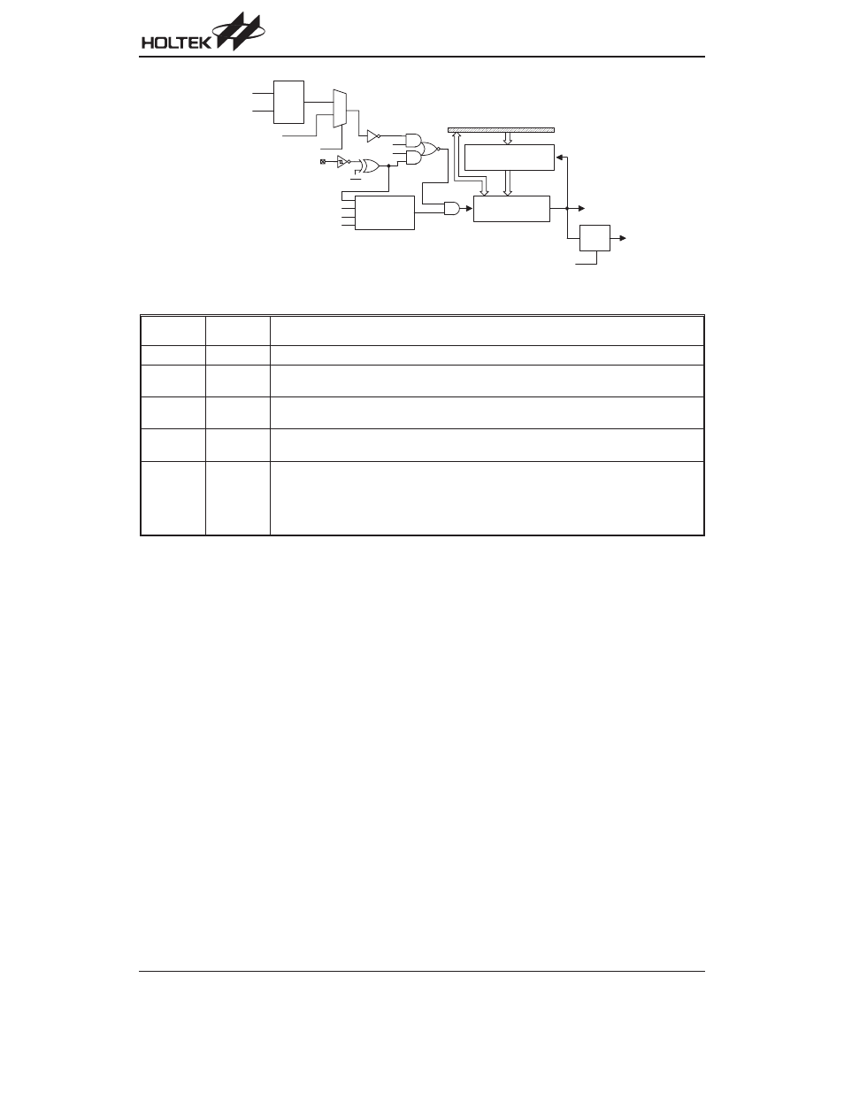
In the event count or timer mode, the timer/event coun-
ter starts counting at the current contents in the
timer/event counter and ends at FFH (FFFFH). Once an
overflow occurs, the counter is reloaded from the
timer/event counter preload register, and generates an
interrupt request flag (T0F; bit 6 of INTC0, T1F; bit 4 of
INTC1).
In the pulse width measurement mode with the values of
the TON and TE bits equal to 1, after the TMR0 (TMR1)
has received a transient from low to high (or high to low
if the TE bit is
²0²), it will start counting until the TMR0
(TMR1) returns to the original level and resets the TON.
The measured result remains in the timer/event counter
even if the activated transient occurs again. In other
words, only 1-cycle measurement can be made until the
TON is set. The cycle measurement will re-function as
long as it receives further transient pulse. In this opera-
tion mode, the timer/event counter begins counting not
according to the logic level but to the transient edges. In
the case of counter overflows, the counter is reloaded
from the timer/event counter register and issues an in-
terrupt request, as in the other two modes, i.e., event
and timer modes.
To enable the counting operation, the Timer ON bit
(TON; bit 4 of TMR0C or TMR1C) should be set to 1. In
the pulse width measurement mode, the TON is auto-
matically cleared after the measurement cycle is com-
pleted. But in the other two modes, the TON can only be
reset by instructions. The overflow of the Timer/Event
Counter 0/1 is one of the wake-up sources and can also
be applied to a PFD (Programmable Frequency Divider)
output at PA3 by options. Only one PFD (PFD0 or
PFD1) can be applied to PA3 by options . No matter
what the operation mode is, writing a 0 to ET0I or ET1I
disables the related interrupt service. When the PFD
function is selected, executing
²CLR [PA].3² instruction
to enable PFD output and executing
²SET [PA].3²
instruction to disable PFD output.
In the case of timer/event counter OFF condition, writing
data to the timer/event counter preload register also re-
loads that data to the timer/event counter. But if the
timer/event counter is turn on, data written to the
timer/event counter is kept only in the timer/event coun-
ter preload register. The timer/event counter still contin-
ues its operation until an overflow occurs.
Label
(TMR0C)
Bits
Function
¾
0~2
Unused bit, read as
²0²
TE
3
Defines the TMR0 active edge of timer/event counter
(0=active on low to high; 1=active on high to low)
TON
4
Enable/disable timer counting
(0=disabled; 1=enabled)
TN2
5
2 to 1 multiplexer control inputs which selects the timer/event counter clock source
(0=RTC outputs; 1= system clock or system clock/4)
TN0
TN1
6
7
Defines the operating mode (TN1, TN0)
01= Event count mode (External clock)
10= Timer mode (Internal clock)
11= Pulse Width measurement mode (External clock)
00= Unused
TMR0C register
T E
S y s t e m C l o c k
T N 1
T N 0
T M R 0
T N 1
T N 0
T O N
P u l s e W
i d t h
M e a s u r e m e n t
M o d e C o n t r o l
T i m e r / E v e n t C o u n t e r 0
P r e l o a d R e g i s t e r
T i m e r / E v e n t
C c o u n t e r 0
D a t a B u s
R e l o a d
O v e r f l o w
t o I n t e r r u p t
R O M
C o d e
O p t i o n
M
U
X
T N 2
S y s t e m C l o c k / 4
T
Q
P F D 0
P A 3 D a t a C T R L
R T C O u t
f
I N T
Timer/Event Counter 0