Rainbow Electronics HT49R70A-1 User Manual
Page 15
HT49R70A-1
Rev. 1.00
15
December 4, 2001
The WDT time-out during HALT differs from other chip
reset conditions, for it can perform a
²warm reset² that
resets only the PC and SP and leaves the other circuits
at their original state. Some registers remain unaffected
during any other reset conditions. Most registers are re-
set to the
²initial condition² once the reset conditions are
met. Examining the PD and TO flags, the program can
distinguish between different
²chip resets².
TO
PD
RESET Conditions
0
0
RES reset during power-up
u
u
RES reset during normal operation
0
1
RES Wake-up HALT
1
u
WDT time-out during normal operation
1
1
WDT Wake-up HALT
Note:
²u² stands for ²unchanged²
To guarantee that the system oscillator is started and
stabilized, the SST (System Start-up Timer) provides an
extra-delay of 1024 system clock pulses when the sys-
tem awakes from the HALT state or during power up.
Awaking from the HALT state or system power-up, the
SST delay is added.
An extra SST delay is added during the power-up pe-
riod, and any wake-up from the HALT may enable only
the SST delay.
The functional unit chip reset status is shown below.
PC
000H
Interrupt
Disabled
Prescaler, Divider
Cleared
WDT, RTC, Time Base
Cleared. After master reset,
WDT starts counting
Timer/event Counter
Off
Input/output Ports
Input mode
SP
Points to the top of the stack
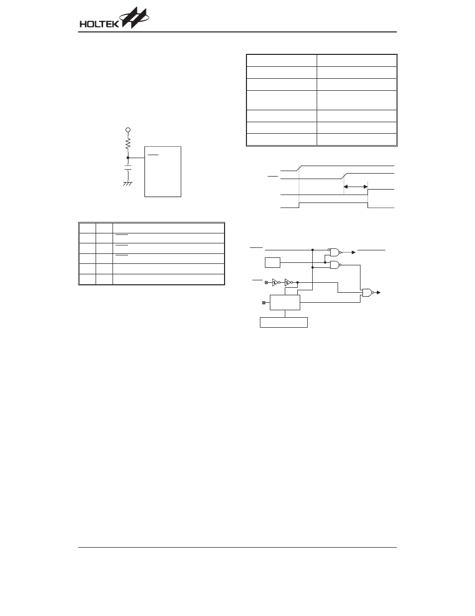
R E S
V
D D
Reset circuit
R E S
V D D
S S T T i m e - o u t
C h i p R e s e t
t
S S T
Reset timing chart
W
D T
H A L T
W
D T
T i m e - o u t
R e s e t
E x t e r n a l
R E S
C o l d
R e s e t
P o w e r - o n D e t e c t i o n
S S T
1 0 - b i t R i p p l e
C o u n t e r
O S C 1
W
a r m R e s e t
Reset configuration