6 using the alarm output gpio6, 7 using the buzzer output gpio7 – Rainbow Electronics GM862-GPS User Manual
Page 65
GM862-GPS Hardware User Guide
1vv0300728 Rev. 8 - 20/09/07
Reproduction forbidden without Telit Communications S.p.A. written authorization - All Rights Reserved
page 65 of 73
10.6 Using the Alarm Output GPIO6
The GPIO6 pin, when configured as Alarm Output, is controlled by the GM862-GPS module and will
rise when the alarm starts and fall after the issue of a dedicated AT command.
This output can be used to power up the GM862-GPS controlling microcontroller or application at the
alarm time, giving you the possibility to program a timely system wake-up to achieve some periodic
actions and completely turn off either the application and the GM862-GPS during sleep periods,
dramatically reducing the sleep consumption to few μA.
In battery powered devices this feature will greatly improve the autonomy of the device.
NOTE: During RESET the line is set to HIGH logic level.
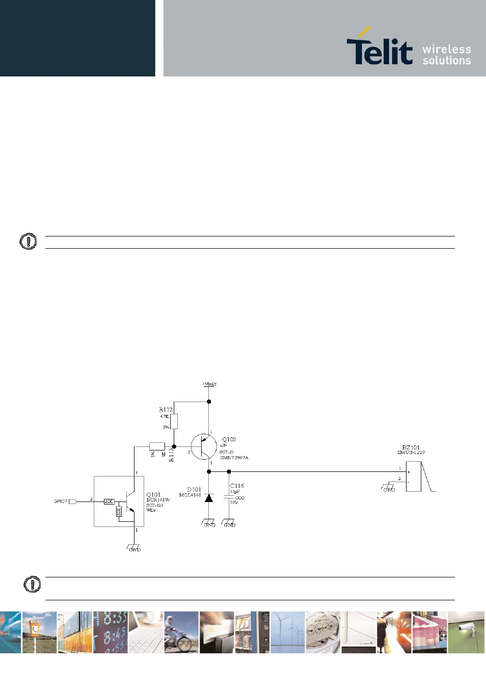
10.7 Using the Buzzer Output GPIO7
The GPIO7 pin, when configured as Buzzer Output, is controlled by the GM862-GPS module and will
drive with appropriate square waves a Buzzer driver.
This permits to your application to easily implement Buzzer feature with ringing tones or melody
played at the call incoming, tone playing on SMS incoming or simply playing a tone or melody when
needed by your application.
A sample interface scheme is included below to give you an idea of how to interface a Buzzer to the
GPIO7:
NOTE: To correctly drive a buzzer a driver must be provided, its characteristics depend on the Buzzer and for them
refer to your buzzer vendor.