Gm862-gps hardware user guide – Rainbow Electronics GM862-GPS User Manual
Page 12
GM862-GPS Hardware User Guide
1vv0300728 Rev. 8 - 20/09/07
Reproduction forbidden without Telit Communications S.p.A. written authorization - All Rights Reserved
page 12 of 73
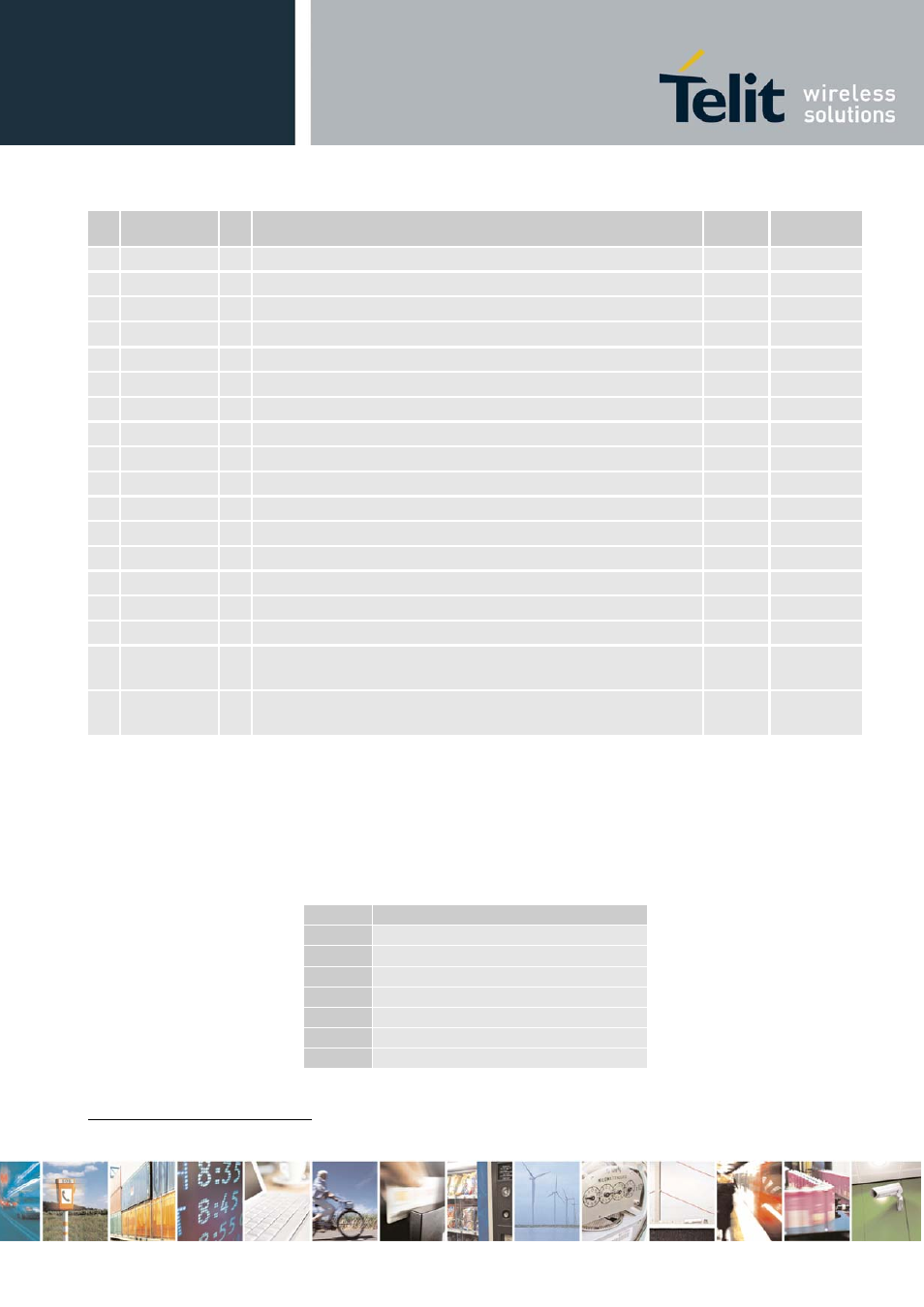
Pin
Signal
I/O Function
Internal
Pull up
Type
33
C107/DSR
O Output for Data set ready signal (DSR) to DTE
CMOS 2.8V
34
GPIO9
I/O Configurable general purpose I/O pin
CMOS 2.8V
35
TX_GPS
O TX Data NMEA GPS protocol
CMOS 2.8V
36
C109/DCD
O Output for Data carrier detect signal (DCD) to DTE
CMOS 2.8V
37
C104/RXD
O Serial data output to DTE
CMOS 2.8V
38
GPIO10/ CLK
I/O Configurable general purpose I/O pin / Python DEBUG 4)
CMOS 2.8V
39
STAT_LED
O Status indicator led
Open Collector
40
GPIO11
I/O Configurable general purpose I/O pin
4.7 Kohm
CMOS 2.8V
41
RX_GPS
I RX Data NMEA GPS protocol
CMOS 2.8V
42
GPIO12
I/O Configurable general purpose I/O pin
47 Kohm
CMOS 2.8V
43
C108/DTR
I Input for Data terminal ready signal (DTR) from DTE
CMOS 2.8V
44 GPIO13 / MRST I/O Configurable general purpose I/O pin / Python DEBUG (4)
CMOS 2.8V
45
C105/RTS
I Input for Request to send signal (RTS) from DTE
CMOS 2.8V
46
GPIO3
I/O Configurable general purpose I/O pin
47 Kohm
CMOS 2.8V
47
GPIO4
I/O Configurable general purpose I/O pin / TX Disable Control
4.7 Kohm
CMOS 2.8V
48
GPIO5 / MTSR I/O Configurable general purpose I/O pin / Python DEBUG (4)
CMOS 2.8V
49
GPIO6
/ ALARM
I/O
Configurable general purpose I/O pin /
ALARM
CMOS 2.8V
50
GPIO7
/ BUZZER
I/O
Configurable general purpose I/O pin /
BUZZER
CMOS 2.8V
(1) For the exclusive use of the Technical Support Service
(2) An earphone with a 150 ohm impedance can be directly connected to EAR+ and EAR–
(3) On this pin a maximum of 10nF bypass capacitor is allowed.
(4) This output requires an external circuit to connect it to a serial port.
Note:
If not used, almost all pins should be left disconnected. The only exceptions are the following
pins:
pin
signal
1,3,5,7
VBATT
2,4,8
GND
17
ON/OFF*
20
TXD
23
RESET*
37
RXD
45
RTS
1
1
RTS should be connected to the GND (on the module side) if flow control is not used