Operation – measuring temperature, Temperature register format figure 2, Temperature/data relationship table 2 – Rainbow Electronics DS1822 User Manual
Page 3
DS1822
3 of 20
OPERATION – MEASURING TEMPERATURE
The core functionality of the DS1822 is its direct-to-digital temperature sensor. The resolution of the
temperature sensor is user-configurable to 9, 10, 11, or 12 bits, corresponding to increments of 0.5
°
C,
0.25
°
C, 0.125
°
C, and 0.0625
°
C, respectively. The default resolution at power-up is 12 bit. The DS1822
powers-up in a low-power idle state; to initiate a temperature measurement and A-to-D conversion, the
master must issue a Convert T [44h] command. Following the conversion, the resulting thermal data is
stored in the 2-byte temperature register in the scratchpad memory and the DS1822 returns to its idle
state. If the DS1822 is powered by an external supply, the master can issue “read time slots” (see the 1-
WIRE BUS SYSTEM section) after the Convert T command and the DS1822 will respond by
transmitting 0 while the temperature conversion is in progress and 1 when the conversion is done. If the
DS1822 is powered with parasite power, this notification technique cannot be used since the bus must be
pulled high by a strong pullup during the entire temperature conversion. The bus requirements for
parasite power are explained in detail in the POWERING THE DS1822 section of this datasheet.
The DS1822 output temperature data is calibrated in degrees centigrade; for Fahrenheit applications, a
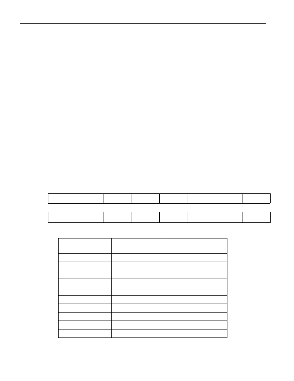
lookup table or conversion routine must be used. The temperature data is stored as a 16-bit sign-extended
two’s complement number in the temperature register (see Figure 2). The sign bits (S) indicate if the
temperature is positive or negative: for positive numbers S = 0 and for negative numbers S = 1. If the
DS1822 is configured for 12-bit resolution, all bits in the temperature register will contain valid data. For
11-bit resolution, bit 0 is undefined. For 10-bit resolution, bits 1 and 0 are undefined, and for 9-bit
resolution bits 2, 1 and 0 are undefined. Table 2 gives examples of digital output data and the
corresponding temperature reading for 12-bit resolution conversions.
TEMPERATURE REGISTER FORMAT Figure 2
bit 7
bit 6
bit 5
bit 4
bit 3
bit 2
bit 1
bit 0
LS Byte
2
3
2
2
2
1
2
0
2
-1
2
-2
2
-3
2
-4
bit 15
bit 14
bit 13
bit 12
bit 11
bit 10
bit 9
bit 8
MS Byte
S S S S S 2
6
2
5
2
4
TEMPERATURE/DATA RELATIONSHIP Table 2
TEMPERATURE DIGITAL
OUTPUT
(Binary)
DIGITAL OUTPUT
(Hex)
+125°C
0000 0111 1101 0000
07D0h
+85°C*
0000 0101 0101 0000
0550h
+25.0625°C
0000 0001 1001 0001
0191h
+10.125°C
0000 0000 1010 0010
00A2h
+0.5°C
0000 0000 0000 1000
0008h
0°C
0000 0000 0000 0000
0000h
-0.5°C
1111 1111 1111 1000
FFF8h
-10.125°C
1111 1111 0101 1110
FF5Eh
-25.0625°C
1111 1110 0110 1111
FE6Fh
-55°C
1111 1100 1001 0000
FC90h
*The power on reset value of the temperature register is +85°C