Rainbow Electronics DS1822 User Manual
Digital thermometer, Features, Pin assignment
1 of 20
043001
FEATURES
•
Unique 1-wire interface requires only one
port pin for communication
•
Each device has a unique 64-bit serial code
stored in an on-board ROM
•
Multi-drop capability simplifies distributed
temperature sensing applications
•
Requires no external components
•
Can be powered from data line. Power supply
range is 3.0V to 5.5V
•
Measures temperatures from –55°C to
+125°C (–67°F to +257°F)
• ±
2.0
°
C accuracy from –10°C to +85°C
•
Thermometer resolution is user-selectable
from 9 to 12 bits
•
Converts temperature to 12-bit digital word in
750 ms (max.)
•
User-definable nonvolatile alarm settings
•
Alarm search command identifies and
addresses devices whose temperature is
outside of programmed limits (temperature
alarm condition)
•
Software compatible with the DS18B20
•
Applications include thermostatic controls,
industrial systems, consumer products,
thermometers, or any thermally sensitive
system
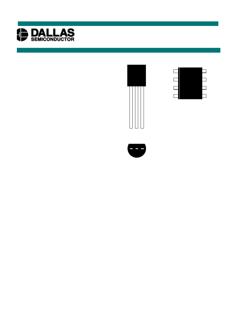
PIN ASSIGNMENT
PIN DESCRIPTION
GND -
Ground
DQ -
Data
In/Out
V
DD
- Power Supply Voltage
NC
- No Connect
DESCRIPTION
The DS1822 Digital Thermometer provides 9 to 12–bit centigrade temperature measurements and has an
alarm function with nonvolatile user-programmable upper and lower trigger points. The DS1822
communicates over a 1-wire bus that by definition requires only one data line (and ground) for
communication with a central microprocessor. It has an operating temperature range of –55°C to +125°C
and is accurate to
±
2.0
°
C over the range of –10°C to +85°C. In addition, the DS1822 can derive power
directly from the data line (“parasite power”), eliminating the need for an external power supply.
Each DS1822 has a unique 64-bit serial code, which allows multiple DS1822s to function on the same 1–
wire bus; thus, it is simple to use one microprocessor to control many DS1822s distributed over a large
area. Applications that can benefit from this feature include HVAC environmental controls, temperature
monitoring systems inside buildings, equipment or machinery, and process monitoring and control
systems.
1
(BOTTOM VIEW)
2 3
DS1822
Econo 1-Wire
®
Digital Thermometer
www.dalsemi.com
8-pin 150-mil SOIC
(DS1822Z)
TO-92
(DS1822)
DALLAS
1822
1
GND
DQ
V
DD
2 3
NC
NC
NC
NC
GND
DQ
V
DD
NC
6
8
7
5
3
1
2
4
DS
1
8
22
Document Outline
- PIN ASSIGNMENT
- PIN DESCRIPTION
- D
- DESCRIPTION
- OVERVIEW
- DS1822 BLOCK DIAGRAM Figure 1
- OPERATION – MEASURING TEMPERATURE
- TEMPERATURE REGISTER FORMAT Figure 2
- TEMPERATURE/DATA RELATIONSHIP Table 2
- OPERATION – ALARM SIGNALING
- TH AND TL REGISTER FORMAT Figure 3
- POWERING THE DS1822
- SUPPLYING THE PARASITE-POWERED DS1822 DURING TEMPERATURE CONVERSIONS Figure 4
- POWERING THE DS1822 WITH AN EXTERNAL SUPPLY Figure 5
- 64-BIT LASERED ROM CODE
- 64-BIT LASERED ROM CODE Figure 6
- MEMORY
- DS1822 MEMORY MAP Figure 7
- CONFIGURATION REGISTER
- Byte 4 of the scratchpad memory contains the configuration register, which is organized as illustrated in Figure 8. The user can set the conversion resolution of the DS1822 using the R0 and R1 bits in this register as shown in Table 3. The power-up de
- CONFIGURATION REGISTER Figure 8
- THERMOMETER RESOLUTION CONFIGURATION Table 3
- CRC GENERATION
- CRC GENERATOR Figure 9
- 1-WIRE BUS SYSTEM
- HARDWARE CONFIGURATION
- HARDWARE CONFIGURATION Figure 10
- TRANSACTION SEQUENCE
- INITIALIZATION
- ROM COMMANDS
- SEARCH ROM [F0h]
- READ ROM [33h]
- MATCH ROM [55h]
- SKIP ROM [CCh]
- ALARM SEARCH [ECh]
- DS1822 FUNCTION COMMANDS
- CONVERT T [44h]
- WRITE SCRATCHPAD [4Eh]
- READ SCRATCHPAD [BEh]
- COPY SCRATCHPAD [48h]
- RECALL E2 [B8h]
- READ POWER SUPPLY [B4h]
- DS1822 FUNCTION COMMAND SET Table 4
- NOTES:
- ROM COMMANDS FLOW CHART Figure 11
- DS1822 FUNCTION COMMANDS FLOW CHART Figure 12
- 1-WIRE SIGNALING
- INITIALIZATION PROCEDURE: RESET AND PRESENCE PULSES
- INITIALIZATION TIMING Figure 13
- READ/WRITE TIME SLOTS
- WRITE TIME SLOTS
- READ/WRITE TIME SLOT TIMING DIAGRAM Figure 14
- READ TIME SLOTS
- DETAILED MASTER READ 1 TIMING Figure 15
- RECOMMENDED MASTER READ 1 TIMING Figure 16
- RELATED APPLICATION NOTES
- DS1822 OPERATION EXAMPLE 1
- DS1822 OPERATION EXAMPLE 2
- ABSOLUTE MAXIMUM RATINGS*
- DC ELECTRICAL CHARACTERISTICS (-55˚C to +125˚C; VDD=3.0V to 5.5V)
- NOTES:
- AC ELECTRICAL CHARACTERISTICS: NV MEMORY
- (-55˚C to +100˚C; VDD=3.0V to 5.5V)
- AC ELECTRICAL CHARACTERISTICS (-55˚C to +125˚C; VDD=3.0V to 5.5V)
- TYPICAL PERFORMANCE CURVE Figure 17
- TIMING DIAGRAMS Figure 18