Bosch, Overload frame – Rainbow Electronics CAN интерфейс User Manual
Page 54
BOSCH
ROBERT BOSCH GmbH, Postfach 300240, D-7000 Stuttgart 30
Sep. 1991
Part B - page 52
At most two OVERLOAD FRAMEs may be generated to delay the next DATA or
REMOTE FRAME.
OVERLOAD FLAG
consists of six ’dominant’ bits. The overall form corresponds to that of the ACTIVE
ERROR FLAG.
The OVERLOAD FLAG’s form destroys the fixed form of the INTERMISSION field. As
a consequence, all other stations also detect an OVERLOAD condition and on their
part start transmission of an OVERLOAD FLAG. In case that there is a ’dominant’ bit
detected during the 3rd bit of INTERMISSION then it will interpret this bit as START OF
FRAME.
Note:
Controllers based on the CAN Specification version 1.0 and 1.1 have another
interpretation of the 3rd bit if INTERMISSION: If a ’dominant’ bit was detected
locally at some node, the other nodes will not interpret the OVERLOAD FLAG
correctly, but interpret the first of these six ’dominant’ bits as START OF
FRAME; the sixth ’dominant’ bit violates the rule of bit stuffing causing an error
condition.
OVERLOAD DELIMITER
consists of eight ’recessive’ bits.
The OVERLOAD DELIMITER is of the same form as the ERROR DELIMITER. After
transmission of an OVERLOAD FLAG the station monitors the bus until it detects a
transition from a ’dominant’ to a ’recessive’ bit. At this point of time every bus station
has finished sending its OVERLOAD FLAG and all stations start transmission of seven
more ’recessive’ bits in coincidence.
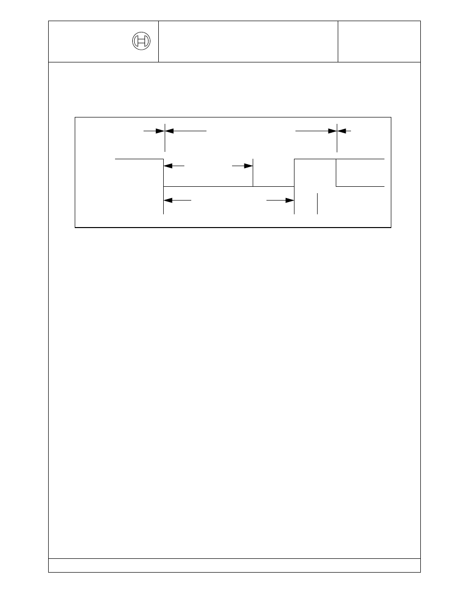
End of Frame or
Overload
Overload Delimiter
Inter
Space or
OVERLOAD FRAME
Overload
Frame
superposition of
Overload Flags
Flag
Frame
Error Delimiter or
Overload Delimiter
Overload Frame