3 error frame, Bosch, Error frame – Rainbow Electronics CAN интерфейс User Manual
Page 52
BOSCH
ROBERT BOSCH GmbH, Postfach 300240, D-7000 Stuttgart 30
Sep. 1991
Part B - page 50
The polarity of the RTR bit indicates whether a transmitted frame is a DATA FRAME
(RTR bit ’dominant’) or a REMOTE FRAME (RTR bit ’recessive’).
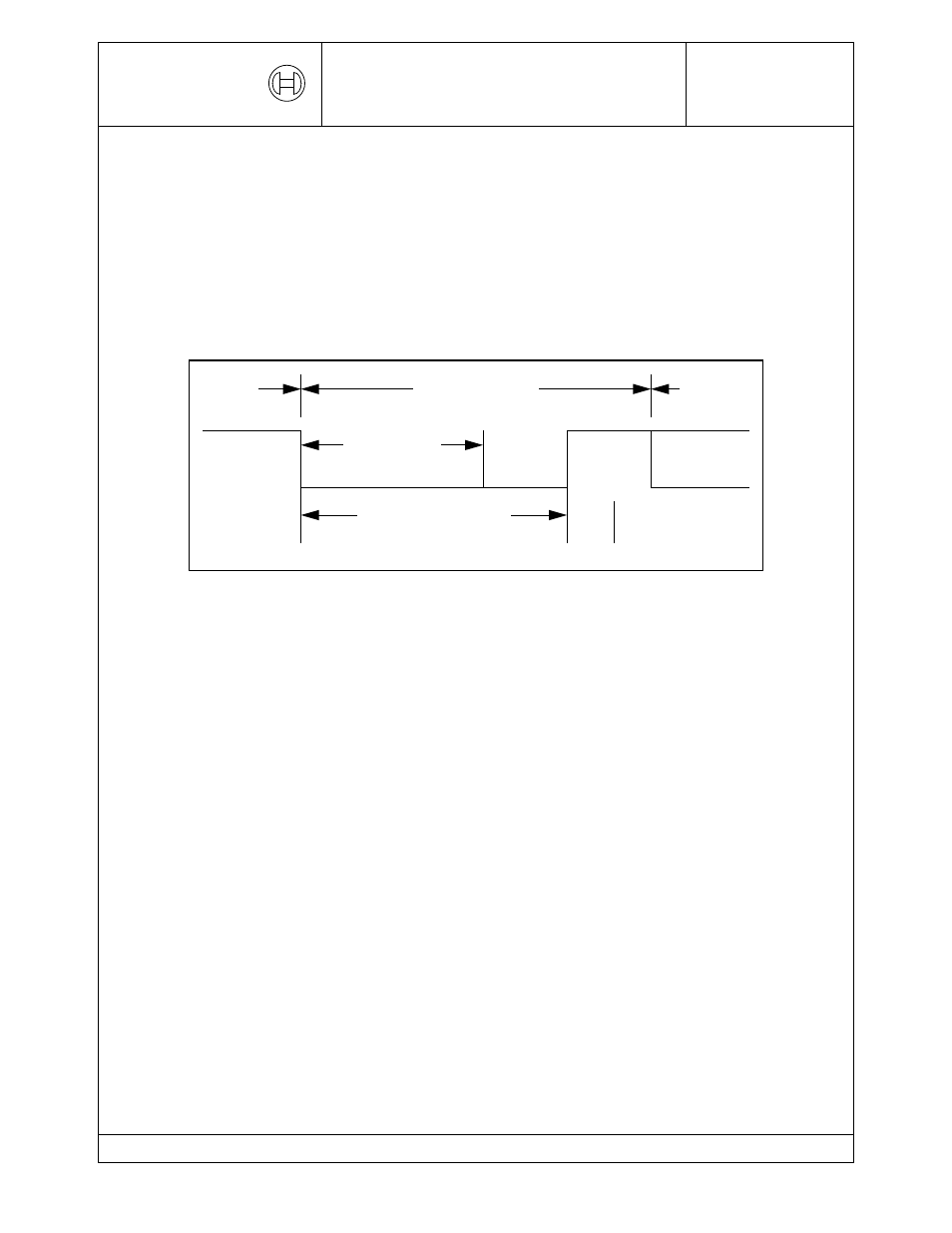
3.2.3 ERROR FRAME
The ERROR FRAME consists of two different fields. The first field is given by the
superposition of ERROR FLAGs contributed from different stations. The following
second field is the ERROR DELIMITER.
In order to terminate an ERROR FRAME correctly, an ’error passive’ node may need
the bus to be ’bus idle’ for at least 3 bit times (if there is a local error at an ’error
passive’ receiver). Therefore the bus should not be loaded to 100%.
ERROR FLAG
There are 2 forms of an ERROR FLAG: an ACTIVE ERROR FLAG and a PASSIVE
ERROR FLAG.
1.
The ACTIVE ERROR FLAG consists of six consecutive ’dominant’ bits.
2.
The PASSIVE ERROR FLAG consists of six consecutive ’recessive’ bits unless it
is overwritten by ’dominant’ bits from other nodes.
An ’error active’ station detecting an error condition signals this by transmission of an
ACTIVE ERROR FLAG. The ERROR FLAG’s form violates the law of bit stuffing (see
CODING) applied to all fields from START OF FRAME to CRC DELIMITER or destroys
the fixed form ACK FIELD or END OF FRAME field. As a consequence, all other
stations detect an error condition and on their part start transmission of an ERROR
Data
Frame
Error Flag
Error Delimiter
Interframe
Space or
ERROR FRAME
Overload
Frame
superposition of
Error Flags
Error Frame