Table 1. functional table, Table 2. transmitter mode, Table 3. receiver mode – Rainbow Electronics DS92LV040A User Manual
Page 6: Test circuits and timing waveforms, Figure 1. differential driver dc test circuit, Figure 1, Applications information
Applications Information
(Continued)
TABLE 1. Functional Table
MODE SELECTED
DE
RE
DRIVER MODE
H
H
RECEIVER MODE
L
L
TRI-STATE
™
MODE
L
H
LOOP BACK MODE
H
L
TABLE 2. Transmitter Mode
INPUTS
OUTPUTS
DE
D
IN
DO+
DO−
H
L
L
H
H
H
H
L
H
0.8V
<
D
IN
<
2.0V
X
X
L
X
Z
Z
TABLE 3. Receiver Mode
INPUTS
OUTPUT
RE
(RI+) – (RI−)
L
L (
<
−70 mV)
L
L
H (
>
0 mV)
H
L
−70 mV
<
V
ID
<
0 mV
X
H
X
Z
X = High or Low logic state
L = Low state
Z = High impedance state
H = High state
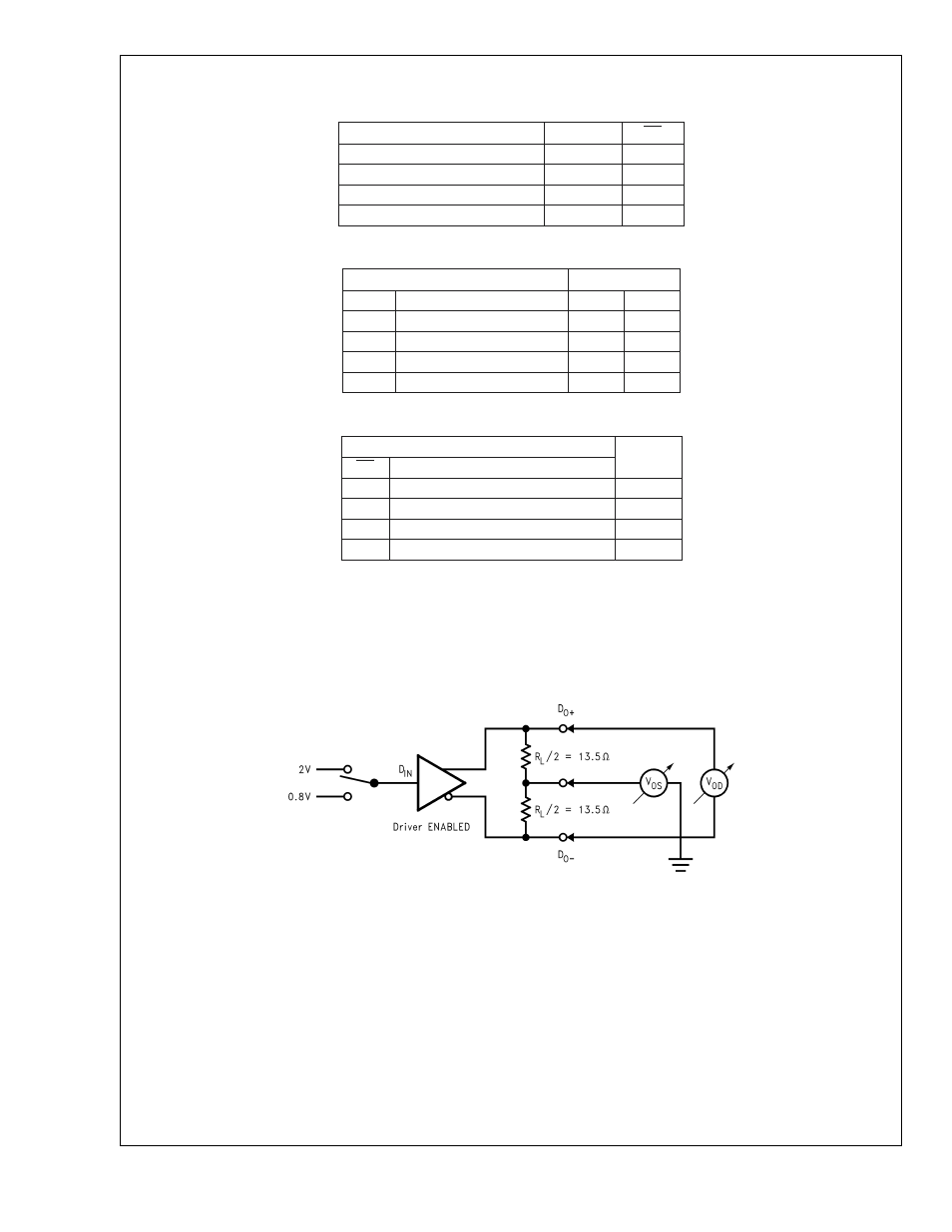
Test Circuits and Timing
Waveforms
10133603
FIGURE 1. Differential Driver DC Test Circuit
DS92L
V040A
www.national.com
6
See also other documents in the category Rainbow Electronics Control panel:
- MAX16840 (1 page)
- MAX9258 (54 pages)
- MAX66140 (21 pages)
- MAX9393 (14 pages)
- MAX66040 (25 pages)
- MAX6981 (1 page)
- MAX6965 (23 pages)
- MAX66100 (16 pages)
- MAX9135 (19 pages)
- MAX66020 (25 pages)
- MAX17127 (22 pages)
- MAX13175E (38 pages)
- MAX16820 (10 pages)
- MAX13237E (16 pages)
- MAX13483E (19 pages)
- MAX13362 (14 pages)
- MAX13486E (16 pages)
- MAX7311 (17 pages)
- MAX8759 (31 pages)
- SCAN92LV090 (13 pages)
- MAX6973 (23 pages)
- MAX13047E (14 pages)
- MAX16831 (20 pages)
- MAX14770E (15 pages)
- MAX11835 (1 page)
- MAX9621 (14 pages)
- MAX9217 (16 pages)
- MAX16841 (18 pages)
- MAX16834 (22 pages)
- MAX7315 (27 pages)
- MAX8645Y (15 pages)
- MAX6975 (23 pages)
- MAX6971 (12 pages)
- MAX3028 (21 pages)
- MAX9395 (13 pages)
- MAX7313 (27 pages)
- MAX6970 (1 page)
- MAX4821 (13 pages)
- MAX4895E (8 pages)
- MAX16823 (13 pages)
- MAX6963 (34 pages)
- MAX9216 (17 pages)
- MAX66000 (21 pages)
- MAX66120 (24 pages)
- MAX13223E (11 pages)