Rainbow Electronics DS1868 User Manual
Page 7
DS1868
7 of 14
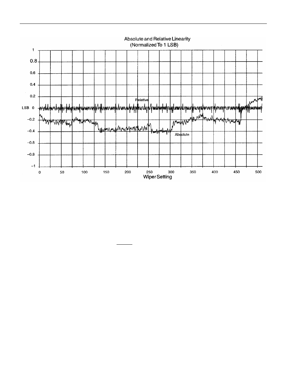
DS1868 ABSOLUTE AND RELATIVE LINEARITY Figure 6
TYPICAL APPLICATION CONFIGURATIONS
Figures 7 and 8 show two typical application configurations for the DS1868. By connecting the wiper
terminal of the part to a high impedance load, the effects of the wiper resistance is minimized, since the
wiper resistance can vary from 400 to 1000 ohms, depending on wiper voltage. Figure 7 presents the
device connected in a variable gain amplifier. The gain of the circuit on Figure 7 is given by the following
equation:
A
V
=
n
-
256
256
+
where n = 0 to 255
Figure 8 shows the device operating in a fixed gain attenuator where the potentiometer is used to
attenuate an incoming signal. Note the resistance R1 is chosen to be much greater than the wiper
resistance to minimize its effect on circuit gain.
- MAX6869 (17 pages)
- TNY-A9260-C01 (5 pages)
- MAX34441 (53 pages)
- MAX4912 (13 pages)
- QIL-A9260-C11 (20 pages)
- QIL-A9260-C11 (1 page)
- QIL-A9260-C11 (34 pages)
- USB-A9263-C02 (1 page)
- DAB-GPS-C01 (15 pages)
- DAB-GPS-C01 (28 pages)
- DAB-CAM-C01 (27 pages)
- DAB-WLS-C01 (WiFi) (20 pages)
- USB-A9G20-C01 (1 page)
- MAX34440 (43 pages)
- SBC35-A9260-C12 (28 pages)
- SBC35-A9260-C12 (1 page)
- MAX16024 (17 pages)
- USB-A9G20-C11 (5 pages)
- DAB-IMU-C01 (20 pages)
- MAX16021 (21 pages)
- DAB-WLS-C11 (BlueTooth) (2 pages)
- SBC35-A9G20-C11 (24 pages)
- MAX16054 (9 pages)
- MAX14525 (7 pages)
- MAX16066 (61 pages)
- USB-A9260-C12 (1 page)
- DS1803 (11 pages)
- DS12887A (2 pages)
- DS1339 (18 pages)
- DS1858 (22 pages)
- DS1267 (12 pages)
- DS12С887A (2 pages)
- DS1804 (7 pages)
- DS1091L (6 pages)
- DS1669S (10 pages)
- DS1867 (14 pages)
- DS1087L (12 pages)
- DS4026 (13 pages)
- DS1286 (13 pages)
- DS1801 (10 pages)
- DS1254 (17 pages)
- DS17887 (38 pages)
- DS1691 (4 pages)
- DS1615 (24 pages)