Absolute and relative linearity, Linearity measurement configuration figure 5 – Rainbow Electronics DS1868 User Manual
Page 6
DS1868
6 of 14
ABSOLUTE AND RELATIVE LINEARITY
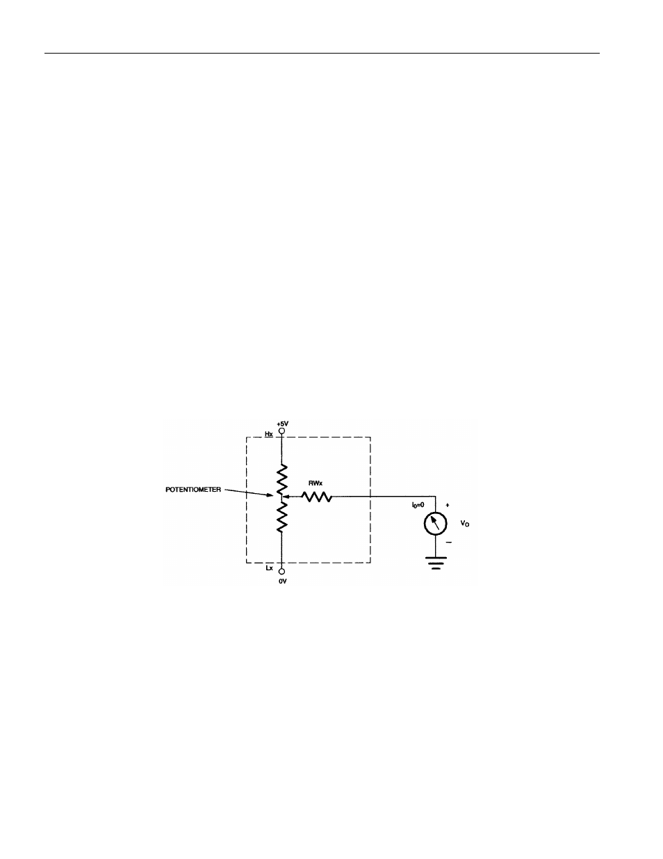
Absolute linearity is defined as the difference between the actual measured output voltage and the
expected output voltage. Figure 5 presents the test circuit used to measure absolute linearity. Absolute
linearity is given in terms of a minimum increment or expected output when the wiper is moved one
position. In the case of the test circuit, a minimum increment (MI) or one LSB would equal 5/256 volts.
The equation for absolute linearity is given as follows:
(1)
ABSOLUTE LINEARITY
AL={V
O
(actual) - V
O
(expected)}/MI
Relative linearity is a measure of error between two adjacent wiper position points and is given in terms
of MI by equation (2).
(2)
RELATIVE LINEARITY
RL={V
O
(n+1) - V
O
(n)}/MI
Figure 6 is a plot of absolute linearity and relative linearity versus wiper position for the DS1868 at 25
°C.
The specification for absolute linearity of the DS1868 is
±0.75 MI typical. The specification for relative
linearity of the DS1868 is
±0.3 MI typical.
LINEARITY MEASUREMENT CONFIGURATION Figure 5