Rainbow Electronics MAX8728 User Manual
Page 2
MAX8728
Low-Cost, Multiple-Output
Power Supply for LCD Monitors/TVs
2
_______________________________________________________________________________________
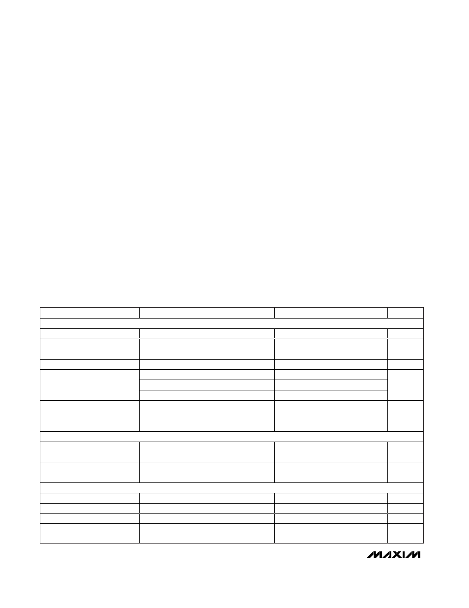
ABSOLUTE MAXIMUM RATINGS
ELECTRICAL CHARACTERISTICS
(Circuit of Figure 1, V
IN
= V
INL
= V
SUPP
= 12V, V
OUT1
= +3.3V, V
SRC
= 28V, GND1 = GND2 = GNDP = GND = 0, I
REF
= 0, T
A
= 0°C
to +85°C. Typical values are at T
A
= +25°C, unless otherwise noted.)
Stresses beyond those listed under “Absolute Maximum Ratings” may cause permanent damage to the device. These are stress ratings only, and functional
operation of the device at these or any other conditions beyond those indicated in the operational sections of the specifications is not implied. Exposure to
absolute maximum rating conditions for extended periods may affect device reliability.
IN, INL, SUPP to GND ............................................-0.3V to +14V
SUPP to IN ..........................................................................±0.3V
DRVP to GNDP.........................................-0.3V to VSUPP + 0.3V
CTL, EN,
SHDN, OUT1, VL, VCC to GND ................-0.3V to +6V
COMP, FB1, FB2, FBN, FBP, FSEL, DEL,
THR, MODE, REF to GND ........................-0.3V to VCC + 0.3V
GND1, GND2, GNDP to GND.............................................±0.3V
BST to GND1 ..........................................................-0.3V to +20V
LX1 to BST................................................................-6V to +0.3V
LX2 to GND2 ..........................................................-0.3V to +19V
DRVN, LX1, GATE to GND1 ..........................-0.3V to VIN + 0.3V
GON, SRC to GND .................................................-0.3V to +40V
SRC to GON ...........................................................-0.3V to +40V
SRC to SUPP ..........................................................-0.3V to +30V
SRC to SUPP (momentary)......................................-14V to +30V
GON to SUPP ..........................................................-14V to +30V
SRC to DRN............................................................-0.3V to +40V
DRN to GND ...........................................................-0.3V to +40V
GON to DRN...........................................................-0.3V to +30V
V
L
Short Circuit to GND ..............................................Momentary
REF Short Circuit to GND ...........................................Continuous
DRVN RMS Current..........................................................-400mA
DRVP RMS Current.........................................................+100mA
LX2 RMS Current ................................................................+1.6A
GND2 RMS Current ............................................................+1.6A
LX1 RMS Current .................................................................-1.6A
Continuous Power Dissipation (T
A
= +70°C)
32-Pin Thin QFN (derate 34.5mW/°C above +70°C) .....2758mW
Operating Temperature Range ...........................-40°C to +85°C
Junction Temperature ......................................................+150°C
Storage Temperature Range .............................-65°C to +160°C
Lead Temperature (soldering, 10s) .................................+300°C
PARAMETER
CONDITIONS
MIN
TYP
MAX
UNITS
GENERAL
IN, INL Input Voltage Range
For VL regulator operation
7.0
12.0
13.2
V
INL Quiescent Current
V
FB2
= V
FBP
= 2.2V, V
FBN
= 0,
LX2 not switching, LX1 switching
7
mA
IN Standby Supply Current
V
IN
= 7V to 13.2V, EN =
SHDN = GND
0.5
mA
FSEL = GND
1275
1500
1730
FSEL = V
CC
850
1000
1150
Switching Frequency
FSEL = REF
425
530
610
kHz
Phase Difference Between
Step-Down/Positive and
Step-Up/Negative Regulators
180
Degrees
VL REGULATOR
VL Output Voltage
7V < V
INL
< 13.2V, V
FB1
= V
FB2
= V
FBP
=
1.9V, V
FBN
= 0.5V, I
VL
= 25mA
4.8
5.0
5.1
V
VL Undervoltage Lockout
Threshold
VL rising, 2.5% hysteresis
3.8
4.0
4.1
V
REFERENCE
REF Output Voltage
No external load
1.98
2.00
2.02
V
REF Load Regulation
0 < I
REF
< 50µA
10
mV
REF Sink Current
REF in regulation
0
10
µA
REF Undervoltage Lockout
Threshold
Rising edge, 200mV hysteresis
1.5
V