High-side gate-drive supply (bst), Enable input (en), soft-start, and soft-stop – Rainbow Electronics MAX15046B User Manual
Page 11
40V, High-Performance, Synchronous
Buck Controller
MAX15046
______________________________________________________________________________________ 11
to function properly. The stray impedance in the gate
discharge path can cause the sense circuitry to interpret
the MOSFET gate as “off” while the V
GS
of the MOSFET
is still high. To minimize stray impedance, use very short,
wide traces.
Synchronous rectification reduces conduction losses in
the rectifier by replacing the normal low-side Schottky
catch diode with a low-resistance MOSFET switch. The
MAX15046 features a robust internal pulldown transistor
with a typical 1I R
DS(ON)
to drive DL low. This low on-
resistance prevents DL from being pulled up during the
fast rise time of the LX node, due to capacitive coupling
from the drain to the gate of the low-side synchronous
rectifier MOSFET.
High-Side Gate-Drive Supply (BST)
An external Schottky diode between BST and DH is
required to boost the gate voltage above LX providing
the necessary gate-to-source voltage to turn on the high-
side MOSFET. The boost capacitor connected between
BST and LX holds up the voltage across the floating gate
driver during the high-side MOSFET on-time.
The charge lost in the boost capacitor for delivering the
gate charge is replenished when the high-side MOSFET
turns off and the LX node goes to ground. When LX is
low, the external diode between V
DRV
and BST recharg-
es the boost capacitor. See the Boost Capacitor and
Diode Selection section in the Applications Information
to choose the right boost capacitor and diode.
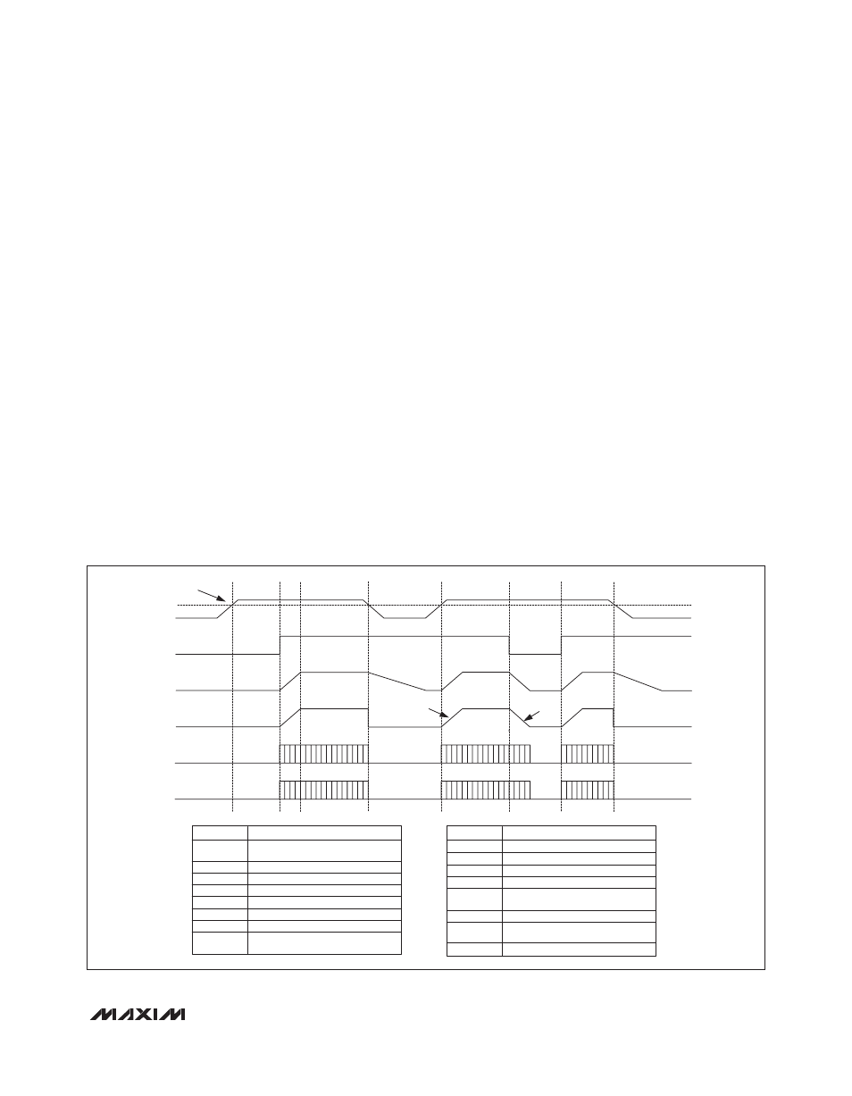
Enable Input (EN), Soft-Start, and Soft-Stop
Drive EN high to turn on the MAX15046. A soft-start
sequence starts to increase (step-wise) the reference
voltage of the error amplifier. The duration of the soft-
start ramp is 2048 switching cycles and the resolution is
1/64th of the steady-state regulation voltage allowing a
smooth increase of the output voltage. A logic-low on EN
initiates a soft-stop sequence by stepping down the ref-
erence voltage of the error amplifier. After the soft-stop
sequence is completed, the MOSFET drivers are both
turned off. See Figure 1.
Connect EN to V
CC
for always-on operation. Owing to
the accurate turn-on/-off thresholds, EN can be used
as a UVLO adjustment input, and for power sequencing
together with the PGOOD outputs.
Figure 1. Power On-Off Sequencing
V
CC
B
C
D
E
2048 CLOCK
CYCLES
2048 CLOCK
CYCLES
F
G
H
I
A
UVLO
EN
V
OUT
DAC_VREF
DH
DL
UVLO
Undervoltage threshold value is provided in
the Electrical Characteristics table.
Internal 5.25V linear regulator output.
Active-high enable input.
Regulator output voltage.
Regulator internal soft-start and soft-stop signal.
Regulator high-side gate-driver output.
Regulator low-side gate-driver output.
V
CC
rising while below the UVLO threshold.
EN is low.
V
CC
EN
V
OUT
DAC_VREF
DH
DL
A
SYMBOL
DEFINITION
B
V
CC
is higher than the UVLO threshold. EN is low.
EN is pulled high. DH and DL start switching.
Normal operation.
V
CC
drops below UVLO.
V
CC
goes above the UVLO threshold. DH and DL
start switching. Normal operation.
EN is pulled low. V
OUT
enters soft-stop.
EN is pulled high. DH and DL start switching.
Normal operation.
V
CC
drops below UVLO.
C
D
E
F
G
H
I
SYMBOL
DEFINITION