Table 5. i, C register: mode2 – Rainbow Electronics MAX8649 User Manual
Page 23
MAX8649
1.8A Step-Down Regulator with Differential
Remote Sense in 2mm x 2mm WLP
______________________________________________________________________________________
23
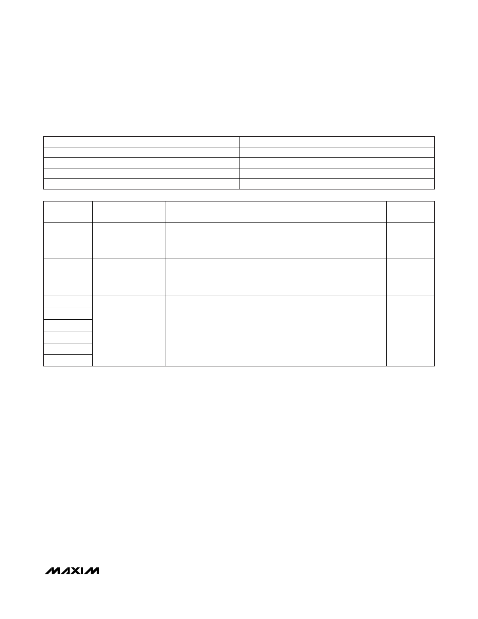
REGISTER NAME
MODE2
Address
0x02h
Reset Value
0xB0h
Type
Read/write
Special Features
Reset upon V
DD
or IN1 UVLO
BIT
NAME
DESCRIPTION
DEFAULT
VALUE
B7 (MSB)
OPERATION_MODE2
DC-DC Step-Down Converter Operation Mode for MODE2
0 = D C - D C conver ter autom ati cal l y chang es b etw een hyster eti c m od e for
l i g ht l oad cond i ti ons and P WM m od e for m ed i um to heavy l oad cond i ti ons.
1 = DC-DC converter operates in forced-PWM mode.
1
B6
SYNC_MODE2
Disable/Enable Synchronization to External Clock
0 = DC-DC converter ignores the external SYNC input regardless of
operation mode.
1 = D C - D C conver ter synchr oni zes to exter nal S Y N C i np ut w hen avai l ab l e.
0
B5
B4
B3
B2
B1
B0 (LSB)
OUT_MODE2[5:0]
Output Voltage Selection for MODE2
000000 = 0.75V
000001 = 0.76V
101110 = 1.21V
101111 = 1.22V
110000 = 1.23V
111110 = 1.37V
111111 = 1.38V
110000
Table 5. I
2
C Register: MODE2
This register contains output voltage and operation mode control for MODE2, VID1 = V
DD
, VID0 = GND.