Max8649 – Rainbow Electronics MAX8649 User Manual
Page 15
MAX8649
Soft-Start
The MAX8649 includes internal soft-start circuitry that
eliminates inrush current at startup, reducing transients
on the input source (see the
Typical Operating Charac-
teristics
). Soft-start is particularly useful for high-imped-
ance input sources, such as Li+ and alkaline cells.
When enabling the MAX8649 into a prebiased output,
the MAX8649 performs a complete soft-start cycle.
Synchronous Rectification
An internal n-channel synchronous rectifier eliminates
the need for an external Schottky diode and improves
efficiency. The synchronous rectifier turns on during the
second half of each switching cycle (off-time). During
this time, the voltage across the inductor is reversed,
and the inductor current ramps down. In PWM mode,
the synchronous rectifier turns off at the end of the
switching cycle. In power-save mode, the synchronous
rectifier turns off when the inductor current falls below
50mA (typ) or at the end of the switching cycle,
whichever occurs first.
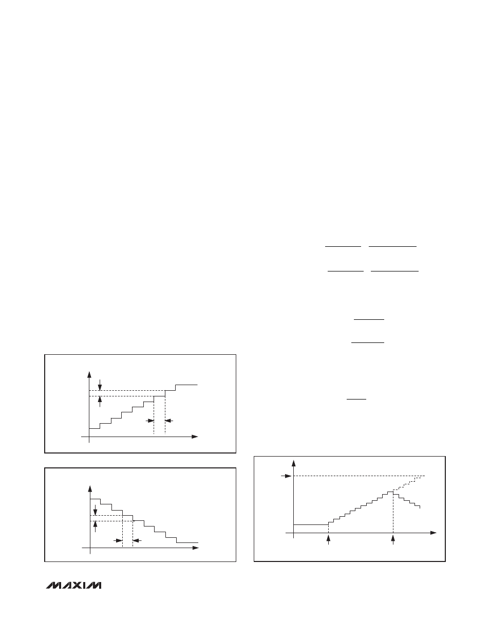
Ramp-Rate Control
The MAX8649 output voltage has an actively controlled
variable ramp rate, set with the I
2
C interface (see
Figures 6, 7, and 8). The value set in the RAMP register
controls the output voltage ramp rate. The
RAMP_DOWN bit controls the active ramp-down
behavior in power-save mode. When the regulator is set
for power-save mode and the RAMP_DOWN bit is
cleared, the ramp-down is not actively controlled, and
the regulator output voltage ramps down at the rate
determined by the output capacitance and the external
load. Small loads result in an output-voltage decay that
is slower than that specified by RAMP; large loads
result in an output-voltage decay that is no faster than
that specified by RAMP When the RAMP_DOWN bit is
set in power-save mode, the zero-cross comparator is
disabled during the ramp-down condition. Active ramp-
down functionality is inherent in forced-PWM operation.
Calculate the maximum and minimum values for the
ramp rate as follows:
where:
f
SW
= 3.25MHz ±10% for PWM operation
f
SW
= 3.25MHz ±25% for hysteretic operation
f
SYNC
= frequency of external clock
n = 4 for 13MHz, 6 for 19.2MHz, and 8 for 26MHz
RAMP_CODE = value of the RAMP[2:0] register (see
Table 9)
f
f
n
SW
SYNC
=
V
mV
t
f
t
f
OUT LSB
CLK MAX
SW MIN
CLK MIN
SW
_
_
_
_
=
=
=
10
1
1
_
_ MAX
t
V
t
t
RAMP MIN
OUT LSB
CLK MAX
RAMP CODE
RAMP
_
_
_
_
=
×
1
2
_
_
_
_
_
MAX
OUT LSB
CLK MIN
RAMP CODE
V
t
=
×
1
2
TIME
OUTPUT
VOLTAGE
DELTA V = 10mV
VOUT1
VOUT2
10mV/RAMP RATE
Figure 6. Ramp-Up Function
TIME
OUTPUT
VOLTAGE
DELTA
V = 10mV
VOUT1
VOUT2
10mV/RAMP
RATE
Figure 7. Ramp-Down Function
FINAL
OUTPUT
VOLTAGE
MODE CHANGE
TO HIGHER VOUT
MODE CHANGE
TO LOWER VOUT
Figure 8. Mode Change Before Final Value is Reached
1.8A Step-Down Regulator with Differential
Remote Sense in 2mm x 2mm WLP
______________________________________________________________________________________
15