Rainbow Electronics MAX8649 User Manual
Page 17
MAX8649
1.8A Step-Down Regulator with Differential
Remote Sense in 2mm x 2mm WLP
______________________________________________________________________________________
17
A START condition from the master signals the begin-
ning of a transmission to the MAX8649. The master ter-
minates transmission by issuing a not acknowledge
followed by a STOP condition (see the
Acknowledge
section for more information). The STOP condition frees
the bus. To issue a series of commands to the slave,
the master can issue REPEATED START (Sr) com-
mands instead of a STOP command to maintain control
of the bus. In general, a REPEATED START command
is functionally equivalent to a regular START command.
When a STOP condition or incorrect address is detect-
ed, the MAX8649 internally disconnects SCL from the
serial interface until the next START condition, minimiz-
ing digital noise and feedthrough.
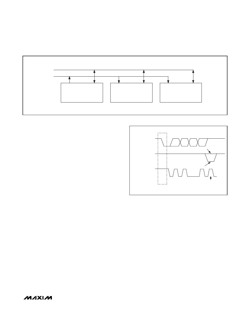
System Configuration
A device on the I
2
C bus that generates a message is
called a transmitter and a device that receives the mes-
sage is a receiver. The device that controls the mes-
sage is the master and the devices that are controlled
by the master are called slaves. See Figure 11.
Acknowledge
The number of data bytes between the START and
STOP conditions for the transmitter and receiver are
unlimited. Each 8-bit byte is followed by an acknowl-
edge bit. The acknowledge bit is a high-level signal put
on SDA by the transmitter during which time the master
generates an extra acknowledge-related clock pulse. A
slave receiver that is addressed must generate an
acknowledge after each byte it receives. Also, a master
receiver must generate an acknowledge after each
byte it receives that has been clocked out of the slave
transmitter. See Figure 12.
The device that acknowledges must pull down the
DATA line during the acknowledge clock pulse, so that
the DATA line is stable low during the high period of the
acknowledge clock pulse (setup and hold times must
also be met). A master receiver must signal an end of
data to the transmitter by not generating an acknowl-
edge on the last byte that has been clocked out of the
slave. In this case, the transmitter must leave SDA high
to enable the master to generate a STOP (P) condition.
Register Reset
The I
2
C resisters reset back to their default values when
the voltage at either IN1 or V
DD
drops below the
corresponding UVLO threshold (see the
Electrical
Characteristics
table).
MASTER
TRANSMITTER/RECEIVER
SLAVE RECEIVER
SLAVE
TRANSMITTER/RECEIVER
SDA
SCL
Figure 11. I
2
CMaster/Slave Configuration
SDA OUTPUT
FROM TRANSMITTER
SDA OUTPUT
FROM RECEIVER
SCL FROM
MASTER
1
2
8
9
ACKNOWLEDGE
CLOCK PULSE FOR
ACKNOWLEDGEMENT
D7
D6
D0
START CONDITION
NOT ACKNOWLEDGE
Figure 12. I
2
C Acknowledge