Rainbow Electronics MAX8649 User Manual
Page 14
MAX8649
1.8A Step-Down Regulator with Differential
Remote Sense in 2mm x 2mm WLP
14
______________________________________________________________________________________
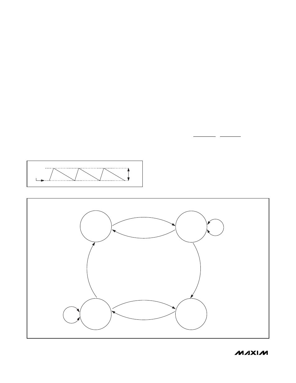
The transition between PWM and hysteretic operation is
based on the number of consecutive zero-crossing
cycles. When more than 16 consecutive zero-crossing
cycles are detected, the DC-DC step-down converter
enables the bias for hysteretic operation. Once correct-
ly biased and the number of consecutive zero-crossing
cycles exceeds 24, the DC-DC step-down converter
begins hysteretic operation.
During hysteretic operation, there is a silent DC offset
due to the use of valley regulation. See Figure 4.
When operating in power-save mode and the load cur-
rent is increased so that the number of consecutive
zero-crossing cycles is less than 16, the PWM mode is
biased. Once fully biased and the number of zero-
crossing cycles drops below 8, the DC-DC converter
then begins PWM operation. Since there is a delay
between the increase in load current and the
DC-DC converter starting PWM, the converter supports
full current on the output during hysteretic operation.
See Figure 5 for a detailed state diagram.
Power-save operation offers improved efficiency at light
loads by changing to hysteretic mode, reducing the
switching frequency depending on the load condition.
With moderate to heavy loading, the regulator switches
at a fixed switching frequency as it does in forced-PWM
mode. In power-save mode, the transition from hys-
teretic mode to fixed-frequency switching occurs at the
load current specified in the following equation:
In forced-PWM mode, the regulator operates with a
constant (3.25MHz or synchronized to external clock
source) switching frequency regardless of output load.
Forced-PWM mode is ideal for low-noise systems
because switching harmonics occur at multiples of the
constant switching frequency and are easily filtered.
However, light-load power consumption in forced-PWM
mode is higher than that of power-save mode.
I
V
V
L
V
V
f
OUT
IN
OUT
OUT
IN
OSC
=
−
Ч
Ч
Ч
2
PWM
MODE
PWM MODE
WITH POWER-SAVE
MODE BIASED
POWER-SAVE
MODE
POWER-SAVE
MODE WITH
PWM BIASED
PWM NOT READY
POWER SAVE NOT READY
MORE THAN 24 CONSECUTIVE
ZERO-CROSSING CYCLES
AND POWER-SAVE MODE READY
LESS THAN 8 CONSECUTIVE
ZERO-CROSSING CYCLES
AND PWM MODE READY
LESS THAN 16 CONSECUTIVE
ZERO-CROSSING CYCLES
MORE THAN 24 CONSECUTIVE
ZERO-CROSSING CYCLES
LESS THAN 8 CONSECUTIVE
ZERO-CROSSING CYCLES
MORE THAN 16 CONSECUTIVE
ZERO-CROSSING CYCLES
Figure 5. Mode Change for DC-DC Step-Down Converter
OUTPUT
RIPPLE
REGULATION
THRESHOLD
Figure 4. Output Regulation in Hysteretic Operation