Rainbow Electronics MAX8649 User Manual
Page 19
MAX8649
1.8A Step-Down Regulator with Differential
Remote Sense in 2mm x 2mm WLP
______________________________________________________________________________________
19
Read Operations
The method for reading a single register (byte) is
shown in Figure 15a. To read a single register:
1) The master sends a start command.
2) The master sends the 7-bit slave address followed
by a write bit.
3) The addressed slave asserts an acknowledge by
pulling SDA low.
4) The master sends an 8-bit register pointer.
5) The slave acknowledges the register pointer.
6) The master sends a repeated START (S) condition.
7) The master sends the 7-bit slave address followed
by a read bit.
8) The slave asserts an acknowledge by pulling SDA low.
9) The slave sends the 8-bit data (contents of the
register).
10) The master asserts a not acknowledge by keeping
SDA high.
11) The master sends a STOP (P) condition.
In addition, the MAX8649 can read a block of multiple
sequential registers as shown in Figure 15b. Use the fol-
lowing procedure to read a sequential block of registers:
1) The master sends a start command.
2) The master sends the 7-bit slave address followed
by a write bit.
3) The addressed slave asserts an acknowledge by
pulling SDA low.
4) The master sends an 8-bit register pointer of the
first register in the block.
5) The slave acknowledges the register pointer.
6) The master sends a repeated START condition.
7) The master sends the 7-bit slave address followed
by a read bit.
8) The slave asserts an acknowledge by pulling SDA low.
9) The slave sends the 8-bit data (contents of the reg-
ister).
10) The master asserts an acknowledge by pulling SDA
low when there is more data to read, or a not
acknowledge by keeping SDA high when all data
has been read.
11) Steps 9 and 10 are repeated for as many registers
in the block, with the register pointer automatically
incremented each time.
12) The master sends a STOP condition.
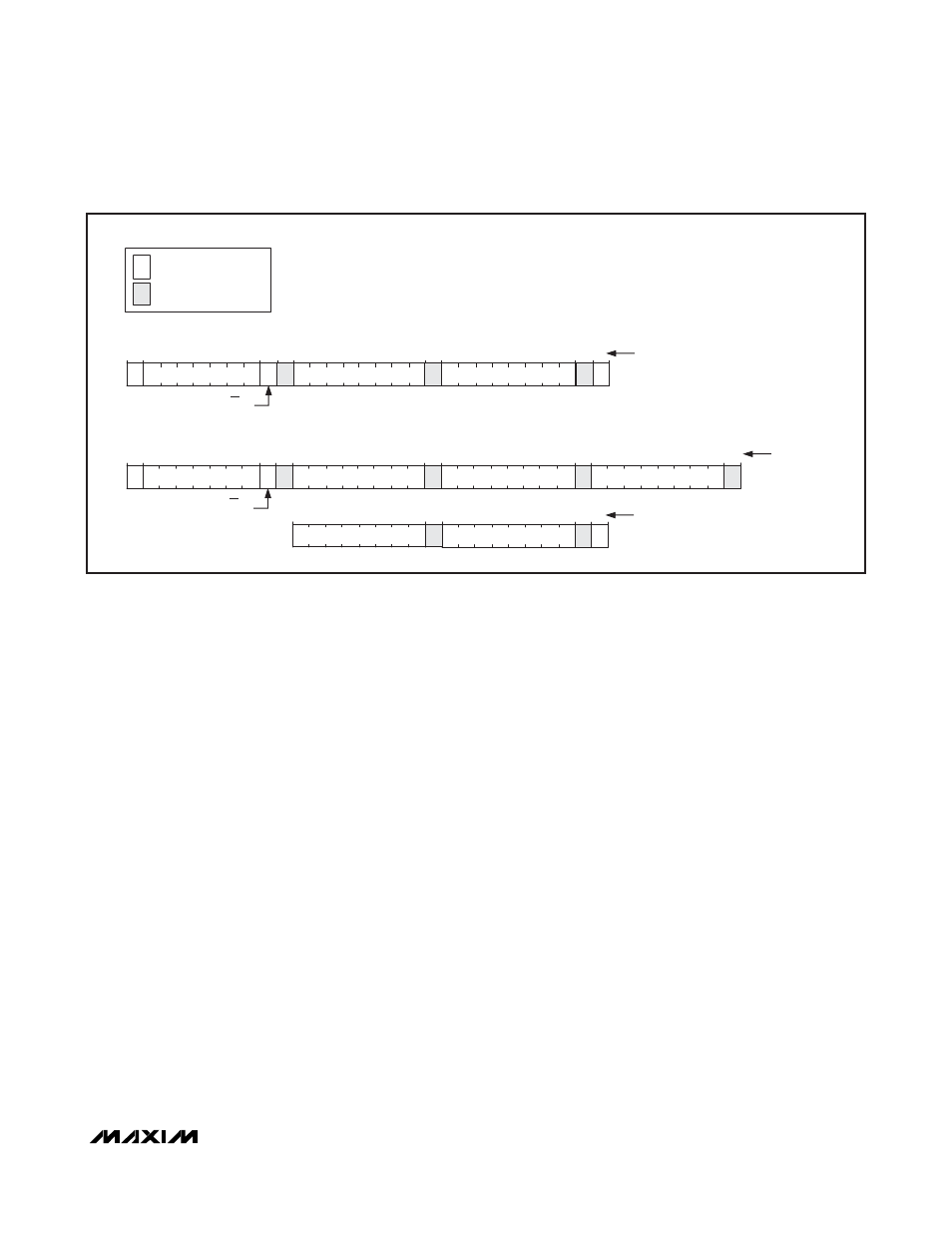
1
S
NUMBER OF BITS
R/W
SLAVE ADDRESS
7
0
1
8
REGISTER POINTER
1
1
SLAVE TO
MASTER
MASTER TO
SLAVE
LEGEND
a) WRITING TO A SINGLE REGISTER WITH THE WRITE BYTE PROTOCOL
1
S
NUMBER OF BITS
R/W
SLAVE ADDRESS
7
0
1
8
REGISTER POINTER X
1
A
1
8
DATA X
1
b) WRITING TO MULTIPLE REGISTERS
...
8
DATA X+n-1
1
NUMBER OF BITS
...
8
DATA X+1
1
A
A
A
A
A
A
8
DATA
1
P
1
A
8
DATA X+n
1
A
P
Figures 14a and 14b. Writing to the MAX8649