Chip information – Rainbow Electronics MAX14753 User Manual
Page 14
MAX14752/MAX14753
8-Channel/Dual 4-Channel
72V Analog Multiplexers
14
______________________________________________________________________________________
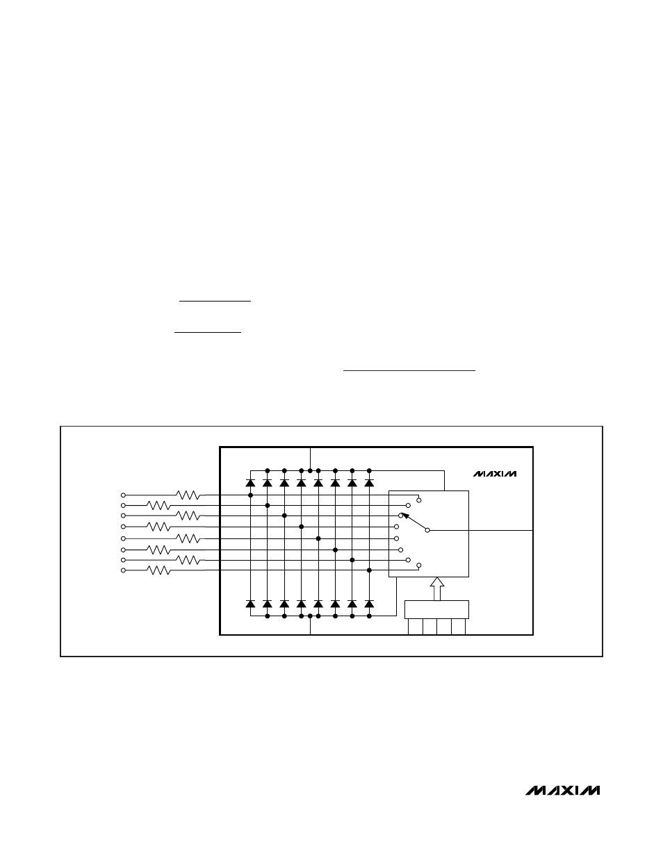
Input Voltage Clamping
For applications that require input voltages beyond the
normal operating voltages, the internal input diodes to
V
DD
and V
SS
can be used to limit the input voltages. As
shown in Figure 13, series resistors can be employed
at the inputs to limit the currents flowing into the diodes
during undervoltage and overvoltage conditions.
Choose the limiting resistors such that the input cur-
rents are limited to I
IN_
(max) = 100mA. The values of
the current limit resistors can be calculated as the larg-
er of R
LIM+
and R
LIM-.
During an undervoltage or overvoltage condition, the
input impedance is equal to R
LIM
. The additional power
dissipation due to the fault currents needs to be calcu-
lated. The MAX14752/MAX14753 multiplexer operates
normally on a channel that is on during an overvoltage
or undervoltage clamping condition on a second chan-
nel that is not switched.
Beyond-the-Rail Input
If input voltages are expected to go beyond the supply
voltages, but within the absolute maximum supply volt-
ages of the MAX14752/MAX14753, add two diodes in
series with the supplies as shown in Figure 14.
During undervoltage and overvoltage events, the internal
diodes pull V
DD
/V
SS
supplies up/down. An advantage of
this scheme is that the input impedance is high and
currents do not flow though the MAX14752/MAX14753
during overvoltage and undervoltage events. The input
voltages must be limited to the voltages specified in the
Absolute Maximum Ratings
section.
Chip Information
PROCESS: CMOS
R
V (max – V
I
(max
R
V
– V (min
I
(max
LIM
IN
DD
IN_
LIM-
SS
IN
IN_
+ =
=
)
)
)
)
MAX14752
OUT
CONTROL
S0
S2
GND
S1
EN
R
LIM
R
LIM
R
LIM
R
LIM
R
LIM
R
LIM
R
LIM
R
LIM
V
SS
V
DD
Figure 13. Input Overvoltage and Undervoltage Clamping