Rainbow Electronics MAX14753 User Manual
General description, Applications, Features
General Description
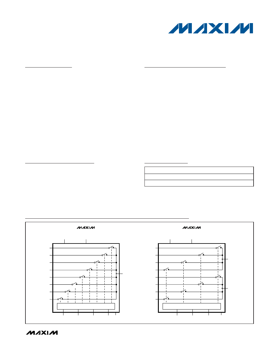
The MAX14752/MAX14753 are 8-to-1 and dual 4-to-1
high-voltage analog multiplexers. Both devices feature
60Ω (typ) on-resistance with 0.03Ω (typ) on-resistance
flatness. These low on-resistance multiplexers conduct
equally well in either direction. Flexible logic levels for
the channel-select interface are defined by the EN input.
The MAX14752 is a 8-to-1 multiplexer and MAX14753 is
a dual 4-to-1 multiplexer. Both devices operate with
dual supplies of ±10V to ±36V, or a single supply of
+20V to +72V.
The MAX14752/MAX14753 are available in a 16-pin
TSSOP package and are pin compatible with the indus-
try-standard DG408/DG409. Both the MAX14752/
MAX14753 are specified over the extended -40°C to
+85°C operating temperature range.
Applications
Programmable-Logic Controllers
Environment Control Systems
ATE Systems
Medical Monitoring Systems
Automotive
Features
♦ Wide Dual Power-Supply Range ±36V (max)
♦ Wide Single Power-Supply Range +72V (max)
♦ Low On-Resistance 60Ω (typ)
♦ R
ON
Flatness Over Common-Mode Voltage 0.03Ω
(typ)
♦ Low-Input (20nA) On-Leakage Current (max)
♦ EN Voltage Defines Logic Level of S0, S1, and S2
♦ Low I
DD
(max) Supply Current in Disable Mode
25µA (max)
♦ Overvoltage/Undervoltage Clamp Through
Protection Diodes
♦ Break-Before-Make Operation
♦ Pin Compatible with Industry-Standard
DG408/DG409
MAX14752/MAX14753
8-Channel/Dual 4-Channel
72V Analog Multiplexers
________________________________________________________________
Maxim Integrated Products
1
19-4255; Rev 0; 8/08
Ordering Information
PART
TEMP RANGE
PIN-PACKAGE
MAX14752EUE+
-40°C to +85°C
16 TSSOP
MAX14753EUE+
-40°C to +85°C
16 TSSOP
+
Denotes a lead-free/RoHS-compliant package.
For pricing, delivery, and ordering information, please contact Maxim Direct at 1-888-629-4642,
or visit Maxim's website at www.maxim-ic.com.
Pin Configurations appear at end of data sheet.
OUT
CONTROL
S1
S0
S2
EN
IN7
IN6
IN5
IN4
IN3
IN2
IN1
IN0
V
DD
V
SS
GND
MAX14752
CONTROL
S1
S0
EN
INB3
INB2
INB1
INB0
INA3
INA2
INA1
INA0
OUTA
V
DD
V
SS
GND
OUTB
MAX14753
Functional Diagrams