Rainbow Electronics MAX14753 User Manual
Page 12
MAX14752/MAX14753
8-Channel/Dual 4-Channel
72V Analog Multiplexers
12
______________________________________________________________________________________
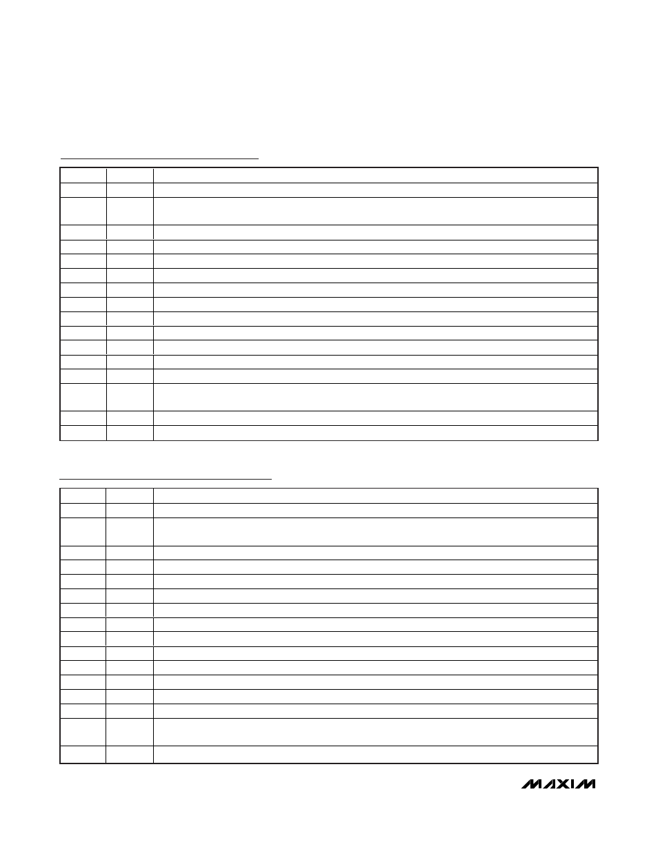
MAX14752 Pin Description (Single 8-to-1 Mux)
PIN
NAME
FUNCTION
1
S0
Mux Input Select
2
EN
Mux Enable. Drive EN high to enable the device. The EN high voltage defines input logic voltage level for
S0, S1, and S2.
3
V
SS
Negative Supply Voltage. Bypass V
SS
to GND with a 1µF ceramic capacitor.
4
IN0
Bidirectional Analog Input
5
IN1
Bidirectional Analog Input
6
IN2
Bidirectional Analog Input
7
IN3
Bidirectional Analog Input
8
OUT
Bidirectional Analog Output
9
IN7
Bidirectional Analog Input
10
IN6
Bidirectional Analog Input
11
IN5
Bidirectional Analog Input
12
IN4
Bidirectional Analog Input
13
V
DD
Positive Supply Voltage. Bypass V
DD
to GND with a 1µF ceramic capacitor.
14
GND
Ground. Connect GND to V
SS
for single supply. Bypass GND to V
SS
with a 1µF ceramic capacitor for dual
supply.
15
S2
Mux Input Select
16
S1
Mux Input Select
PIN
NAME
FUNCTION
1
S0
Mux Input Select
2
EN
Mux Enable. Drive EN high to enable the device. The EN high voltage defines input logic voltage level for
S0 and S1.
3
V
SS
Negative Supply Voltage. Bypass V
SS
to GND with a 1µF ceramic capacitor.
4
INA0
Bidirectional Analog Input
5
INA1
Bidirectional Analog Input
6
INA2
Bidirectional Analog Input
7
INA3
Bidirectional Analog Input
8
OUTA
Bidirectional Analog Output
9
OUTB
Bidirectional Analog Output
10
INB3
Bidirectional Analog Input
11
INB2
Bidirectional Analog Input
12
INB1
Bidirectional Analog Input
13
INB0
Bidirectional Analog Input
14
V
DD
Positive Supply Voltage. Bypass V
DD
to GND with a 1µF ceramic capacitor.
15
GND
Ground. Connect GND to V
SS
for single supply. Bypass GND to V
SS
with a 1µF ceramic capacitor for dual
supply.
16
S1
Mux Input Select
MAX14753 Pin Description (Dual 4-to-1 Mux)