Detailed description, Applications information, Current through the mux – Rainbow Electronics MAX14753 User Manual
Page 13: Signal’s slew-rate limit
MAX14752/MAX14753
8-Channel/Dual 4-Channel
72V Analog Multiplexers
______________________________________________________________________________________
13
Detailed Description
The MAX14752/MAX14753 are 8-to-1 and dual 4-to-1
high-voltage analog multiplexers. Both devices feature
60Ω (typ) on-resistance with 0.03Ω (typ) on-resistance
flatness. These low on-resistance multiplexers conduct
equally well in either direction.
The MAX14752 is an 8-to-1 multiplexer and MAX14753
is a dual 4-to-1 multiplexer. Both devices operate with
dual supplies of ±10V to ±36V or a single supply of
+20V to +72V. Both devices can also operate with
unbalanced supplies, such as +36V and -10V. These
multiplexers support rail-to-rail input and output signals.
The control logic level is defined via the EN input.
These devices do not require power-supply sequenc-
ing. For input voltage steps larger than 15V, the input-
signal slew rate needs to be limited as described in the
Applications Information
section, otherwise the device
can be damaged.
Applications Information
Current Through the Mux
The current flowing through each on-channel of the
MAX14752/MAX14753 multiplexers must be limited to
±5mA for normal operation. If the current exceeds this
limit, an internal leakage current from that channel to
V
SS
appears. Larger input current does not destroy the
device if the max power dissipation is not exceeded.
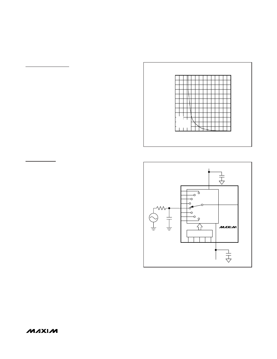
Signal’s Slew-Rate Limit
If the input signal to the MAX14752/MAX14753 is a volt-
age step larger than 15V, limit the slew rate of the sig-
nal according to the safe operating area specified in
Figure 11. For input-voltage steps lower than 15V (posi-
tive or negative), slew-rate limiting is not required. Slew-
rate limiting can be achieved through a passive RC
lowpass filter (see Figure 12). Do not use the input volt-
age steps beyond the safe operating area specified in
the Figure 11 to avoid permanent damage to the device.
INPUT SLEW-RATE SOA
INPUT VOLTAGE STEP (V)
INPUT SLEW RATE (V/
μ
s)
40
50
60
55
65
100
140
180
220
260
300
60
120
160
200
240
280
80
0
70
45
5
15
25
20
30 35
10
SAFE
OPERATING
AREA (SOA)
Figure 11. Safe Operating Area
MAX14752
OUT
V
DD
1nF
500
Ω
IN0
IN1
IN2
IN3
IN5
IN6
IN7
IN4
1
μF
CONTROL
S0
S2
GND
S1
EN
V
SS
1
μF
Figure 12. Input Slew-Rate Limit