Timing diagrams, Test circuits – Rainbow Electronics MAX13223E User Manual
Page 5
MAX13223E
±70V Fault-Protected, 3.0V to 5.5V,
2Tx/2Rx RS-232 Transceiver
_______________________________________________________________________________________
5
0
t
PTHL
0
V
0
-V
0
T_IN
T_OUT
-3V
3V
t
F
t
R
0
3V
-3V
V
CC
/2
t
PTLH
V
CC
/2
V
CC
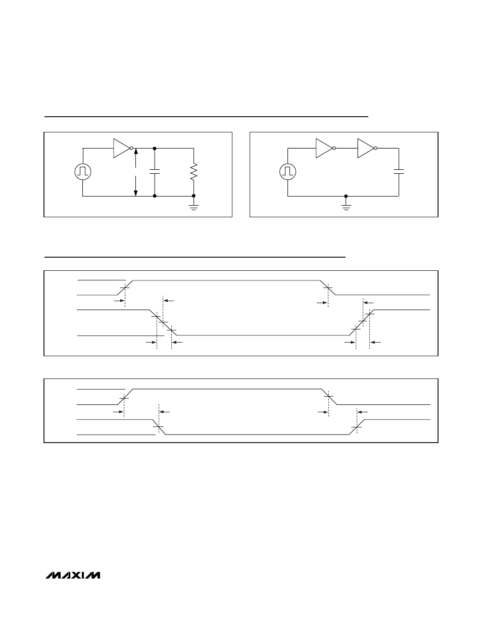
Figure 3. Driver Propagation Delay
t
PRHL
t
PRLH
1.3V
1.7V
V
CC
/2
V
CC
/2
V
IL
V
0H
V
0L
R_IN
R_OUT
V
IH
t
R
, t
F
≤ 10ns
Figure 4. Receiver Propagation Delay
Timing Diagrams
C
L
R
L
V
O
T_IN
T_OUT
Figure 1. Driver Test Circuit
T_IN
T_OUT R_IN
15pF
Figure 2. Receiver Test Circuit
Test Circuits
See also other documents in the category Rainbow Electronics Control panel:
- MAX16840 (1 page)
- MAX9258 (54 pages)
- MAX66140 (21 pages)
- MAX9393 (14 pages)
- MAX66040 (25 pages)
- MAX6981 (1 page)
- MAX6965 (23 pages)
- MAX66100 (16 pages)
- MAX9135 (19 pages)
- MAX66020 (25 pages)
- MAX17127 (22 pages)
- MAX13175E (38 pages)
- MAX16820 (10 pages)
- MAX13237E (16 pages)
- MAX13483E (19 pages)
- MAX13362 (14 pages)
- MAX13486E (16 pages)
- MAX7311 (17 pages)
- MAX8759 (31 pages)
- SCAN92LV090 (13 pages)
- MAX6973 (23 pages)
- MAX13047E (14 pages)
- MAX16831 (20 pages)
- MAX14770E (15 pages)
- MAX11835 (1 page)
- MAX9621 (14 pages)
- MAX9217 (16 pages)
- MAX16841 (18 pages)
- MAX16834 (22 pages)
- MAX7315 (27 pages)
- MAX8645Y (15 pages)
- MAX6975 (23 pages)
- MAX6971 (12 pages)
- MAX3028 (21 pages)
- MAX9395 (13 pages)
- MAX7313 (27 pages)
- MAX6970 (1 page)
- MAX4821 (13 pages)
- MAX4895E (8 pages)
- MAX16823 (13 pages)
- MAX6963 (34 pages)
- MAX9216 (17 pages)
- MAX66000 (21 pages)
- MAX66120 (24 pages)