Fault protection, 8kv esd protection, Esd test conditions – Rainbow Electronics MAX13223E User Manual
Page 10: Human body model
MAX13223E
Fault Protection
The MAX13223E is designed to survive faults such as
direct shorts to power supplies, miswiring faults, con-
nector failures, and tool misapplications of the transmit-
ter outputs and receiver inputs to voltages in the ±70V
range without damage. This fault protection is applica-
ble in all modes of the MAX13223E: active, shutdown,
and powered down. Both receivers operate over the
±70V input range, but the termination resistor (R
RX,I
)
increases when |V
R_IN
| voltage exceeds ±32V.
A receiver’s input termination resistor reduces to its
nominal value if the input voltage reduces to within the
±24V range. The receiver inputs and transmitter out-
puts are independently fault protected.
±8kV ESD Protection
As with all Maxim devices, ESD-protection structures
are incorporated on all pins to protect against electro-
static discharges encountered during handling and
assembly. In using the MAX13223E, C4 must be a 1µF
capacitor for the extended ESD protection. The driver
outputs and receiver inputs of the MAX13223E have
extra protection against static electricity. Maxim’s engi-
neers have developed state-of-the-art structures to pro-
tect these pins against ESD of ±8kV without damage.
The ESD structures withstand high ESD in all states:
normal operation, shutdown, and powered down. After
an ESD event, Maxim’s E versions keep working without
latchup, whereas competing RS-232 products can latch
and must be powered down to remove latchup. ESD
protection can be tested in various ways. The transmit-
ter outputs and receiver inputs of this product family are
characterized for protection to the following limits:
1) ±8kV using the Human Body Model
2) ±8kV using the Contact-Discharge Method speci-
fied in IEC 61000-4-2
ESD Test Conditions
ESD performance depends on a variety of conditions.
Contact Maxim for a reliability report that documents
test setup, test methodology, and test results.
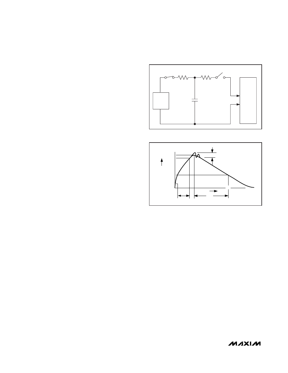
Human Body Model
Figure 8a shows the Human Body Model and Figure 8b
shows the current waveform it generates when dis-
charged into a low impedance. This model consists of a
100pF capacitor charged to the ESD voltage of interest,
which is then discharged into the test device through a
1.5k
Ω resistor.
IEC 61000-4-2
The IEC 61000-4-2 standard covers ESD testing and
performance of finished equipment. It does not specifi-
cally refer to integrated circuits. The major difference
between tests done using the Human Body Model and
IEC 61000-4-2 is higher peak current in IEC 61000-4-2,
because series resistance is lower in the IEC 61000-4-2
model. Hence, the ESD withstand voltage measured to
IEC 61000-4-2 is generally lower than that measured
using the Human Body Model. Figure 9a shows the IEC
61000-4-2 model and Figure 9b shows the current
waveform for the ±8kV, IEC 61000-4-2, level 4, ESD
Contact-Discharge Method.
±70V Fault-Protected, 3.0V to 5.5V,
2Tx/2Rx RS-232 Transceiver
10
______________________________________________________________________________________
CHARGE-CURRENT
LIMIT RESISTOR
DISCHARGE
RESISTANCE
STORAGE
CAPACITOR
Cs
100pF
R
C
1M
Ω
R
D
1500
Ω
HIGH-
VOLTAGE
DC
SOURCE
DEVICE
UNDER
TEST
Figure 8a. Human Body ESD Test Model
I
P
100%
90%
36.8%
t
RL
TIME
t
DL
CURRENT WAVEFORM
PEAK-TO-PEAK RINGING
(NOT DRAWN TO SCALE)
Ir
10%
0
0
AMPERES
Figure 8b. Human Body Current Waveform