Clock circuitry, Reset circuitry, Power circuitry – Rainbow Electronics SBC35-A9G20-C11 User Manual
Page 11: Remote communication
1x 32Kbytes of internal ROM
2x 4Kbytes of internal SRAM
1x 64Kbytes SPI EEPROM memory
1x 64Mbytes of SDRAM memory (32 bits bus width)
1x 256Mbytes of NAND Flash memory (8bits bus width)
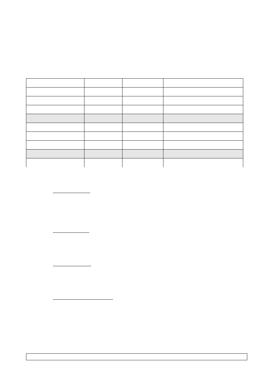
Bank
Start address
Size
Description
Internal memories
0x00000000
256Mbytes
EBI CS0
0x10000000
256Mbytes
Expansion connectors
EBI CS1 (SDRAMC)
0x20000000
64Mbytes
Soldered SDRAM
EBI CS2
0x30000000
Not available
EBI CS3 (NAND)
0x40000000
256Mbytes
Soldered NAND Flash
EBI CS4 (CF slot 0)
0x50000000
-
Compact Flash Interface
EBI CS5
0x60000000
256Mbytes
Expansion connectors
EBI CS6
0x70000000
Not available
EBI CS7
0x80000000
256Mbytes
Expansion connectors
1.3. Clock Circuitry
12Mhz standard oscillator
Selectable 32768Hz low power external standard crystal Oscillator or internal low power
RC oscillator
1.4. Reset Circuitry
Internal reset controller with bi-directional reset pin
External reset pushbutton
1.5. Power Circuitry
On board 1.0V low dropout linear regulator
On board 3.3V low dropout linear regulator
1.6. Remote Communication
1x complete modem serial interface (COM Port 0) via RS232 DB9 male connector
2x additional serial interfaces with RTS/CTS handshake control via HE10-2x5 connector
(TTL level signals)
1x DBGU serial port TTL via HE10-2x5 (TTL level signals)
2x USB Host ports V2.0 full speed compliant, 12Mbits per second (UHP)
1x USB V2.0 full speed compliant, 12Mbits per second (UDP)
Datasheet USG-00019-A01
11/24