Table 1. input select truth table, Table 2. loopback select truth table – Rainbow Electronics MAX9395 User Manual
Page 9
Balanced cables such as twisted pair offer superior
signal quality and tend to generate less EMI due to
canceling effects.
Board Layout
Use a four-layer printed circuit (PC) board providing
separate signal, power, and ground planes for high-
speed signaling applications. Bypass V
CC
to GND as
close to the device as possible. Install termination
resistors as close to receiver inputs as possible. Match
the electrical length of the differential traces to minimize
signal skew.
MAX9394/MAX9395
2:1 Multiplexers and 1:2 Demultiplexers with
Loopback
_______________________________________________________________________________________
9
LOGIC INPUTS
DIFFERENTIAL OUTPUTS
LB_SELA
LB_SELB
BSEL
OUTA_ /
OUTA_
OUTB /
OUTB
0
0
0
INA selected
INB0 selected
0
0
1
INA selected
INB1 selected
0
1
X
INA selected
INA selected
1
0
0
INB0 selected
INB0 selected
1
0
1
INB1 selected
INB1 selected
1
1
0
INB0 selected
INA selected
1
1
1
INB1 selected
INA selected
Table 1. Input Select Truth Table
LB_SEL_
OUT_ _
GND or open
Normal inputs selected.
V
CC
Loopback inputs selected.
Table 2. Loopback Select Truth Table
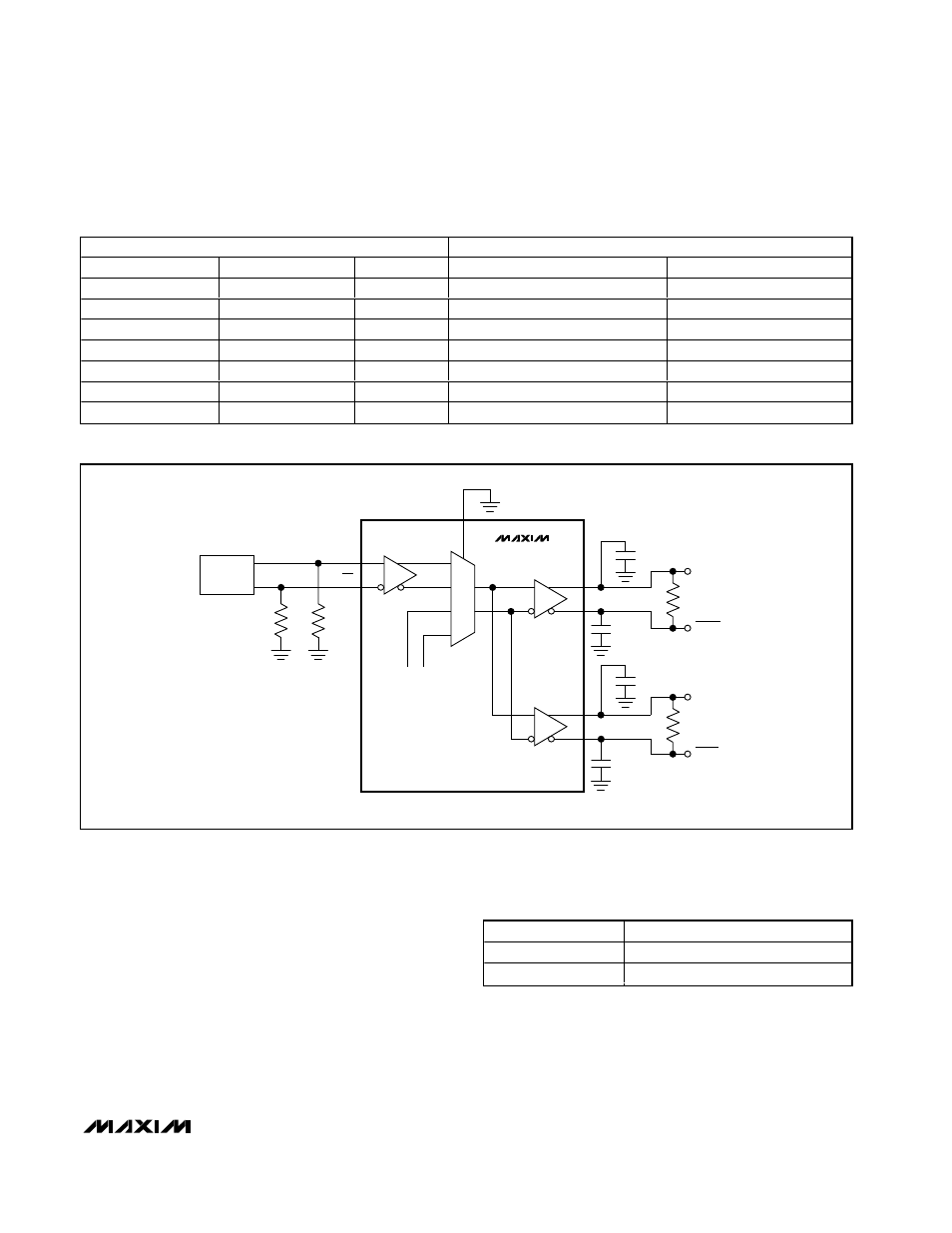
LB_SELA
0
LB
PULSE
GENERATOR
OUTA0
OUTA0
OUTA1
OUTA1
C
L
R
L
R
L
INA
INA
50
Ω
C
L
50
Ω
C
L
C
L
MAX9394
MAX9395
ENA0 = ENA1 = HIGH
1 CHANNEL SHOWN.
FROM
CHANNEL B
R
L
= 100
Ω ±1%
C
L
= 1.0pF
Figure 5. Output Transition Time, Propagation Delay, and Output Channel-to-Channel Skew Test Circuit
X = Don’t care.