Charge pump, Click-and-pop suppression, Rf susceptibility – Rainbow Electronics MAX9820 User Manual
Page 9
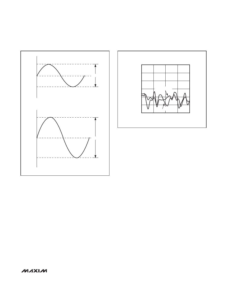
GND (Figure 1). With no DC component, there is no
need for the large DC-blocking capacitors. The
MAX9820 charge pump requires two small ceramic
capacitors, conserving board space, reducing cost,
and improving the frequency response of the head-
phone amplifier.
Charge Pump
The MAX9820 features a low-noise charge pump. The
500kHz (typ) charge pump switching frequency is well
beyond the audio range and does not interfere with
audio signals.
Click-and-Pop Suppression
In conventional single-supply audio amplifiers, the out-
put-coupling capacitor contributes significantly to audi-
ble clicks and pops. Upon startup, the amplifier
charges the coupling capacitor to its bias voltage, typi-
cally half the supply. Likewise, on shutdown, the capac-
itor is discharged. This results in a DC shift across the
capacitor, which appears as an audible transient at the
speaker. Since DirectDrive biases the outputs at
ground, this problem does not arise. Additionally, the
MAX9820 features extensive click-and-pop suppres-
sion that eliminates any audible transient sources inter-
nal to the device.
RF Susceptibility
Modern audio systems are often subject to RF radiation
from sources such as wireless and cellular phone net-
works. Although the RF radiation is out of the audio
band, many signals, GSM signals in particular, contain
bursts or modulation at audible frequencies. Most ana-
log amplifiers demodulate the low-frequency envelope,
adding noise to the audio signal. The MAX9820 archi-
tecture addresses the RF susceptibility problem by
rejecting RF noise and preventing it from coupling into
the audio band.
MAX9820
DirectDrive Headphone Amplifier
with External Gain
_______________________________________________________________________________________
9
V
OUT
CONVENTIONAL DRIVER OUTPUT WAVEFORMS
V
DD
GND
V
DD
/2
V
DD
V
OUT
MAX9820 OUTPUT WAVEFORMS
V
DD
-V
DD
GND
2V
DD
Figure 1. Conventional Driver Output Waveform vs. MAX9820
Output Waveform
RF IMMUNITY vs. FREQUENCY
MAX9820 fig02
FREQUENCY (GHz)
RF IMMUNITY (dBV)
2.45
1.90
1.35
-100
-80
-60
-40
-20
0
-120
0.8
3.00
LEFT CHANNEL
RIGHT CHANNEL
Figure 2. MAX9820 RF Susceptibility