Max9820, Directdrive headphone amplifier with external gain, Applications information – Rainbow Electronics MAX9820 User Manual
Page 10: Table 2. suggested capacitor vendors
MAX9820
Shutdown
The MAX9820 features a low-power shutdown mode
that reduces quiescent current consumption to less
than 1µA, extending battery life for portable applica-
tions. Drive SHDN low to disable the amplifiers and the
charge pump. In shutdown mode, the amplifier output
impedance is set to 600
Ω || R
FB
. The amplifiers and
charge pump are enabled once SHDN is driven high.
Applications Information
Power Dissipation
Under normal operating conditions, linear power ampli-
fiers can dissipate a significant amount of power. The
maximum power dissipation for each package is given
in the
Absolute Maximum Ratings
section or can be cal-
culated by the following equation:
where T
J(MAX)
is +150°C, T
A
is the ambient tempera-
ture, and
θ
JA
is the reciprocal of the derating factor in
°C/W as specified in the
Absolute Maximum Ratings
section.
The MAX9820 has two power dissipation sources: a
charge pump and the two output amplifiers. If power
dissipation for a given application exceeds the maxi-
mum allowed package power dissipation, reduce V
DD
,
increase load impedance, decrease the ambient tem-
perature, or add heatsinking to the device. Large out-
put, supply, and ground traces decrease
θ
JA
, allowing
more heat to be transferred from the package to the
surrounding air.
Thermal-overload protection limits total power dissipa-
tion in the MAX9820. When the junction temperature
exceeds 145°C (typ), the thermal protection circuitry
disables the amplifier output stage. The amplifiers are
enabled once the junction temperature cools by
approximately 15°C.
Undervoltage Lockout (UVLO)
The MAX9820 features a UVLO function that prevents
the device from operating if the supply voltage falls
below 2.2V (min). This feature ensures proper operation
during brownout conditions and prevents deep battery
discharge. Once the supply voltage reaches the mini-
mum supply voltage range, the MAX9820 charge pump
is turned on and the amplifiers are powered, provided
that SHDN is high.
Component Selection
Input-Coupling Capacitor
The input capacitor (C
IN
), in conjunction with the input
resistor (R
IN
), forms a highpass filter that removes the
DC bias from an incoming signal (see the
Functional
Diagram/Typical Operating Circuit
). The AC-coupling
capacitor allows the device to bias the signal to an opti-
mum DC level. Assuming zero-source impedance, the
-3dB point of the highpass filter is given by:
Choose the C
IN
such that f
-3dB
is well below the lowest
frequency of interest. Setting f
-3dB
too high affects the
device’s low-frequency response. Use capacitors
whose dielectrics have low-voltage coefficients, such
as tantalum or aluminum electrolytic. Capacitors with
high-voltage coefficients, such as ceramics, can result
in increased distortion at low frequencies.
Charge-Pump Capacitor Selection
Use ceramic capacitors with a low ESR for optimum
performance. For optimal performance over the extend-
ed temperature range, select capacitors with an X7R or
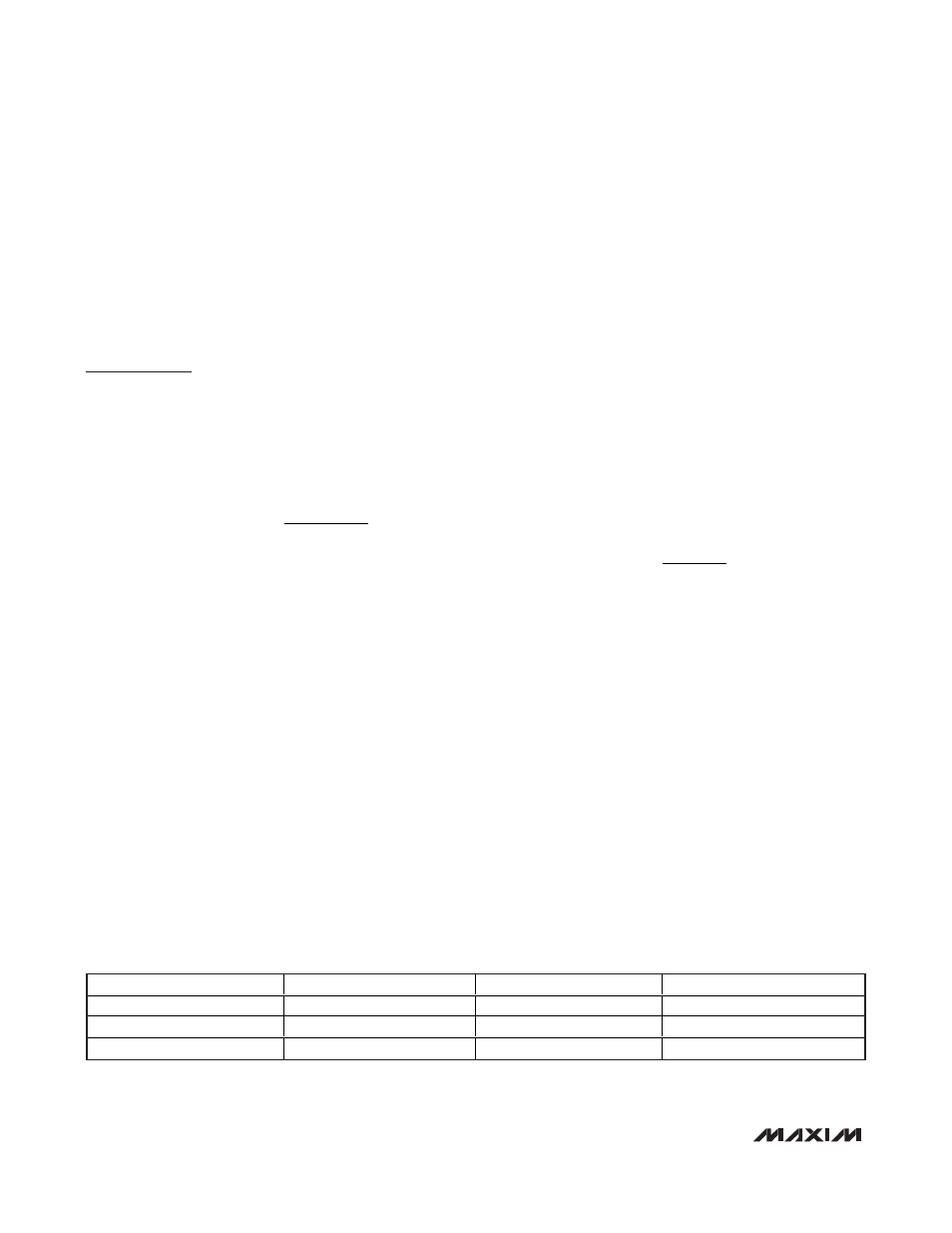
X5R dielectric. Table 2 lists suggested manufacturers.
f
R C
dB
IN IN
−
=
3
1
2
π
P
T
T
DISSPKG MAX
J MAX
A
JA
(
)
(
)
=
−
θ
DirectDrive Headphone Amplifier
with External Gain
10
______________________________________________________________________________________
SUPPLIER
PHONE
FAX
WEBSITE
Taiyo Yuden
800-348-2496
847-925-0899
www.t-yuden.com
TDK
847-803-6100
847-390-4405
www.component.tdk.com
Murata
770-436-1300
770-436-3030
www.murata.com
Table 2. Suggested Capacitor Vendors