Application information – Rainbow Electronics ADC08161 User Manual
Page 11
Application Information
1.0 FUNCTIONAL DESCRIPTION
The ADC08161 performs an 8-bit analog-to-digital conver-
sion using a multi-step flash technique. The first flash gener-
ates the five most significant bits (MSBs) and the second
flash generates the three least significant bits (LSBs).
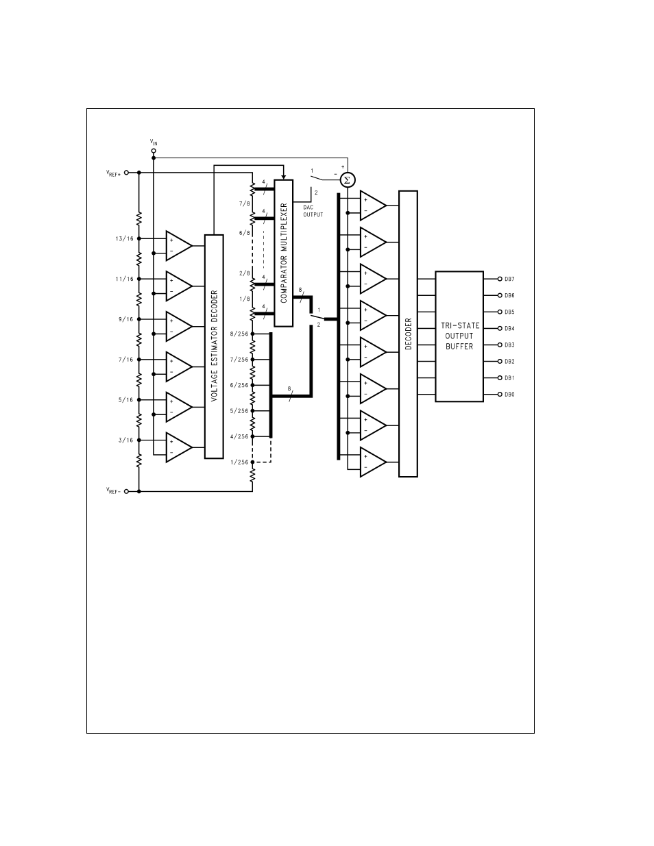
Figure
6
shows the major functional blocks of the ADC08161
multi-step flash converter. It consists of an over-encoded
2
1
⁄
2
-bit Voltage Estimator, an internal DAC with two different
voltage spans, a 3-bit half-flash converter and a comparator
multiplexer.
The resistor string near the center of the block diagram in
Figure 6
forms the internal main DAC. Each of the eight re-
sistors at the bottom of the string is equal to 1/256 of the total
string resistance. These resistors form the LSB Ladder and
have a voltage drop of 1/256 of the total reference voltage
(V
REF+
− V
REF−
) across them. The remaining resistors make
up the MSB Ladder . They are made up of eight groups of
four resistors connected in series. Each MSB Ladder section
has
1
⁄
8
of the total reference voltage across it. Within a given
MSB Ladder section, each of the MSB resistors has 8/256,
or
1
⁄
3
2 of the total reference voltage across it. Tap points are
found between all of the resistors in both the MSB and LSB
Ladders. Through the Comparator Multiplexer these tap
points can be connected, in groups of eight, to the eight com-
parators shown at the right of
Figure 6
. This function pro-
vides the necessary reference voltages to the comparators
during each flash conversion.
The six comparators, seven-resistor string (estimator DAC),
and Estimator Decoder at the left of
Figure 6
form the Volt-
age Estimator. The estimator DAC connected between
V
REF+
and V
REF−
generates the reference voltages for the
six Voltage Estimator comparators. These comparators per-
form a very low resolution A/D conversion to obtain an “esti-
mate” of the input voltage. This estimate is then used to con-
trol the Comparator Multiplexer, connecting the appropriate
MSB Ladder section to the eight flash comparators. Only 14
comparators, six in the Voltage Estimator and eight in the
flash converter, are needed to achieve the full eight-bit reso-
lution, instead of 32 comparators that would be needed by
traditional half-flash methods.
A conversion begins with the Voltage Estimator comparing
the analog input signal against the six tap voltages on the es-
timator DAC. The estimator decoder then selects one of the
groups of tap points along the MSB Ladder. These eight tap
DS011149-17
FIGURE 6. Block Diagram of the ADC08161 Multi-Step Flash Architecture
11
www.national.com