Detailed description, Applications information, Pin description – Rainbow Electronics MAX9610 User Manual
Page 6
MAX9610
1µA, µDFN/SC70, Lithium-Ion Battery,
Precision Current-Sense Amplifier
6
_______________________________________________________________________________________
Detailed Description
The MAX9610 family of unidirectional high-side, cur-
rent-sense amplifiers features a 1.6V to 5.5V input com-
mon-mode range. The input range is excellent for
monitoring the current of a single-cell lithium-ion battery
(Li+), which at full charge is 4.2V, typically 3.6V in nor-
mal use, and less than 2.9V when ready to be
recharged. The MAX9610 is ideal for many battery-
powered, handheld devices because it uses only 1μA
quiescent supply current to extend battery life. The
MAX9610 monitors current through a current-sense
resistor and amplifies the voltage across that resistor.
See the
Typical Operating Circuit
on page 1.
The MAX9610 is a unidirectional current-sense amplifier
that has a well-established history. An op amp is used
to force the current through an internal gain resistor at
RS+ that has a value of R
1
, such that its voltage drop
equals the voltage drop across an external sense resis-
tor, R
SENSE
. There is an internal resistor at RS- with the
same value as R
1
to minimize offset voltage. The cur-
rent through R
1
is sourced by a pFET. Its drain current
is the same as its source current that flows through a
second gain resistor, R
OUT
. This produces an output
voltage, V
OUT
, whose magnitude is I
LOAD
x R
SENSE
x
R
OUT
/R
1
. The gain accuracy is based on the matching
of the two gain resistors R
1
and R
OUT
(see Table 1).
Total gain = 25V/V for the MAX9610T, 50V/V for the
MAX9610F, and 100V/V for the MAX9610H.
Applications Information
Choosing the Sense Resistor
Choose R
SENSE
based on the following criteria.
Voltage Loss
A high R
SENSE
value causes the power-source voltage
to drop due to IR loss. For minimal voltage loss, use the
lowest R
SENSE
value.
OUT Swing vs. V
RS+
and V
SENSE
The MAX9610 is unique since the supply voltage is the
input common-mode voltage (the average voltage at
RS+ and RS-). There is no separate V
CC
supply voltage
input. Therefore, the OUT voltage swing is limited by
the minimum voltage at RS+.
V
OUT(MAX)
= V
RS+(MAX)
- V
SENSE(MAX)
- V
OH
and
V
SENSE
full scale should be less than V
OUT
/gain at the
minimum RS+ voltage. For best performance with a
3.6V supply voltage, select R
SENSE
to provide approxi-
mately 120mV (gain of 25V/V), 60mV (gain of 50V/V), or
30mV (gain of 100V/V) of sense voltage for the full-
scale current in each application. These can be
increased by use of a higher minimum input voltage.
Accuracy
In the linear region (V
OUT
< V
OUT(MAX)
), there are two
components to accuracy: input offset voltage (V
OS
) and
Gain Error (GE). The MAX9610 has V
OS
= 500μV (max)
and Gain Error of 0.5% (max). Use the following linear
equation to calculate total error.
V
OUT
= (Gain ± GE) x V
SENSE
± (Gain x V
OS
)
A high R
SENSE
value allows lower currents to be mea-
sured more accurately because offsets are less signifi-
cant when the sense voltage is larger.
Efficiency and Power Dissipation
At high current levels, the I
2
R loss in R
SENSE
can be
significant. Take this into consideration when choosing
the resistor value and its power dissipation (wattage)
rating. Also, the sense resistor’s value might drift if it is
allowed to heat up excessively. The precision V
OS
of
the MAX9610 allows the use of small sense resistors to
reduce power dissipation and reduce hot spots.
R
V
G
I
SENSE
OUT
LOAD
=
×
(max)
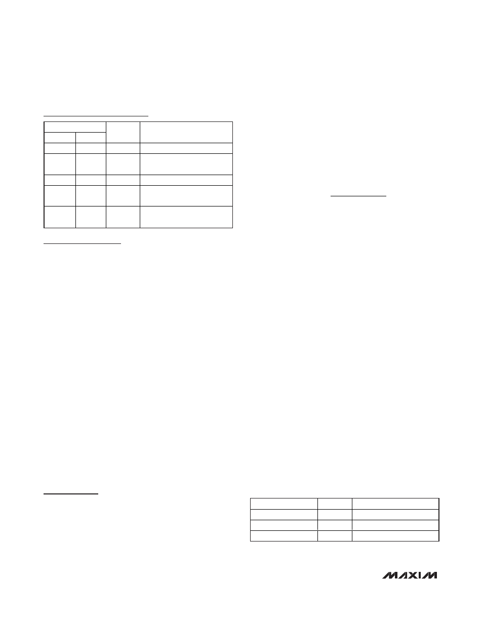
Pin Description
PIN
µDFN
SC70
NAME
FUNCTION
1
1, 2
GND
Ground
2, 5
—
N.C.
No Connection. Not internally
connected.
3
3
OUT
Output
4
4
RS-
Load-Side Connection to
External Sense Resistor
6
5
RS+
Power-Side Connection to
External Sense Resistor
GAIN (V/V)
R
1
(
Ω)
R
OUT
(
Ω)
100
100
10k
50
200
10k
25
400
10k
Table 1. MAX9610, Internal Gain Setting
Resistors (Typical Values)