Max7457 video switch for dual scart connectors, Pin description, Detailed description – Rainbow Electronics MAX7457 User Manual
Page 5
MAX7457
Video Switch for Dual SCART Connectors
_______________________________________________________________________________________
5
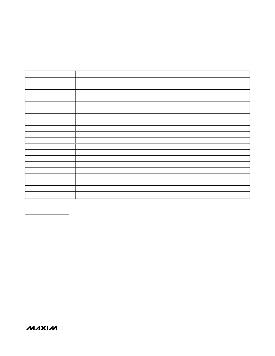
Pin Description
PIN
NAME
FUNCTION
1
INB
Channel INB Video Input. Use channel INB for the red (R) signal. AC-couple INB with a series
0.1µF capacitor.
2
INC
Channel INC Video Input. Use channel INC for the green (G) signal. AC-couple INC with a series
0.1µF capacitor.
3
IND
Channel IND Video Input. Use channel IND for the blue (B) signal. AC-couple IND with a series
0.1µF capacitor.
4
DISABLE
Disable Logic Input. A logic low on DISABLE enables the output buffers. A logic high on DISABLE
disables all buffer outputs and puts them in a high-impedance state.
5
SELA
Select A Input. A logic low on SELA selects INA1 and a logic high on SELA selects INA2.
6, 8, 14
N.C.
No Connection. Not internally connected.
7
GND
Ground
9
V
CC
+5V Supply Input
10
OUTD
Channel D Video Output. OUTD can be either AC- or DC-coupled.
11
OUTC
Channel C Video Output. OUTC can be either AC- or DC-coupled.
12
OUTB
Channel B Video Output. OUTB can be either AC- or DC-coupled.
13
OUTA
Channel A Video Output. OUTA can be either AC- or DC-coupled.
15
INA2
Channel INA2 Video Input. Connect auxiliary CVBS to INA2. AC-couple INA2 with a series
0.1µF capacitor.
16
INA1
Channel INA1 Video Input. Connect CVBS to INA1. AC-couple INA1 with a series 0.1µF capacitor.
—
EP
Exposed Pad. Connect to GND for improved thermal heat sinking.
Detailed Description
The MAX7457 4-channel video switch filters and
buffers video encoder DAC outputs in applications
such as STBs, HDRs, DVD players, and digital VCRs.
The MAX7457 offers an auxiliary CVBS loop-through
feature required in dual SCART applications. Audio and
video switching in SCART STBs utilize a costly integrat-
ed A/V switch offering high-end features such as vol-
ume control and high audio-drive capability. A more
cost-effective solution uses the MAX7457 for the video
switching along with low-cost standard passive analog
switches for the audio switching.
The MAX7457 reconstructs and cleans up analog video
signals from the video encoder’s DAC output. Each
channel consists of a lowpass filter and an output video
buffer that drives two standard 150
Ω video loads. The
MAX7457 operates from a single +5V supply and has a
nominal cutoff frequency of 5MHz, optimized for NTSC,
PAL, and SDTV.
Filter
Filter Response
The reconstruction filter consists of two 2nd-order
Sallen-Key stages. The Butterworth-type response fea-
tures a maximally flat passband for NTSC and PAL
bandwidths. The stopband offers at least 43dB (typ) of
attenuation at the video encoder’s DAC sampling fre-
quency of 27MHz (see the Typical Operating
Characteristics).
High-Frequency Boost
INA1/INA2 have +1.2dB of high-frequency boost that
increases image sharpness by compensating for sig-
nal degradation and rolloff in the video encoder.
Channels INB/INC/IND (RGB) do not boost high-fre-
quency signals and have a flat response over the
video bandwidth.