Applications information – Rainbow Electronics MAX15051 User Manual
Page 11
MAX15050/MAX15051
High-Efficiency, 4A, 1MHz, Step-Down Regulators
with Integrated Switches in 2mm x 2mm Package
______________________________________________________________________________________
11
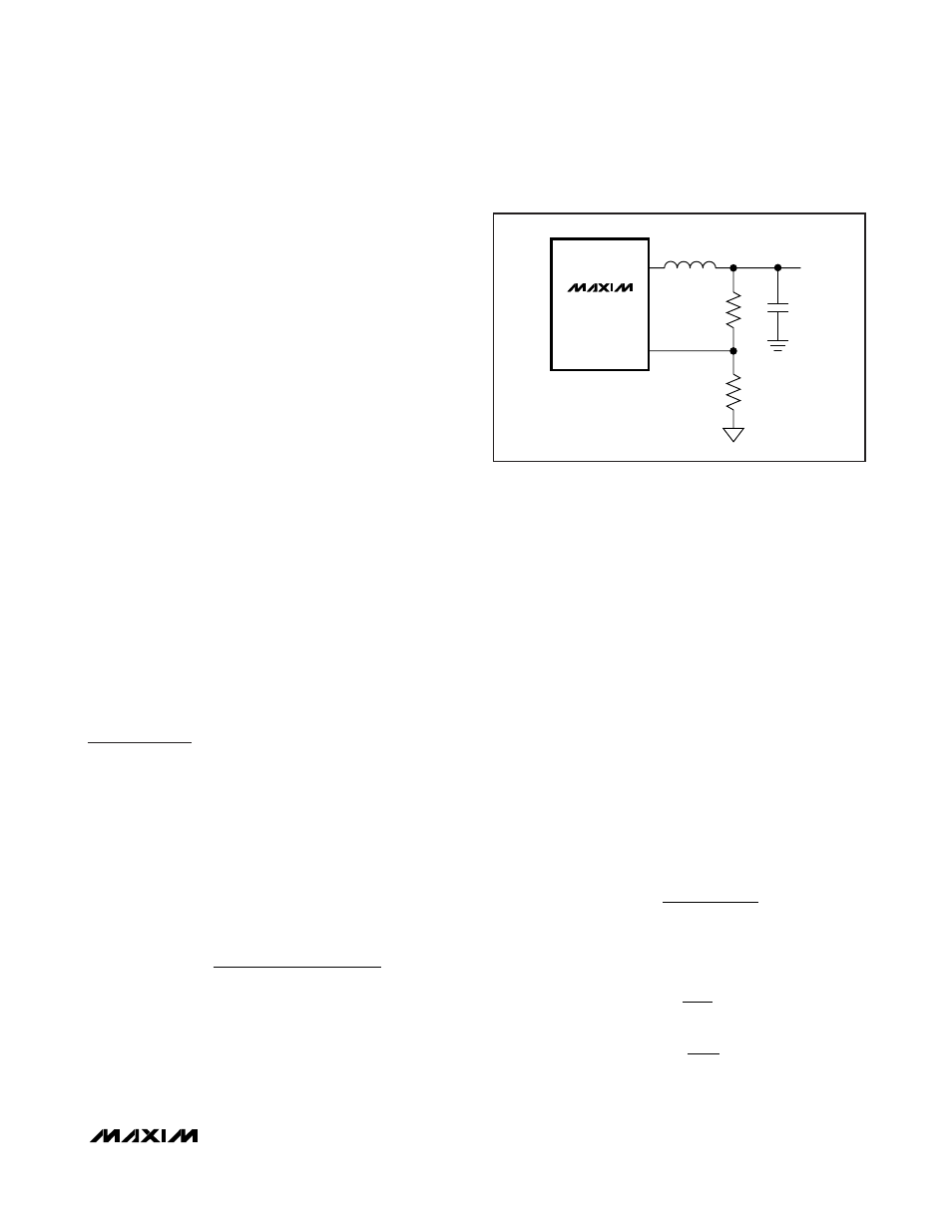
Setting the Output Voltage
The MAX15050/MAX15051 output voltage is adjustable
from 0.6V to 90% of V
IN
by connecting FB to the center
tap of a resistor-divider between the output and GND
(Figure 3). To determine the values of the resistor-
divider, first select the value of R3 between 2k
Ω and
10k
Ω. Then use the following equation to calculate R4:
R4 = (V
FB
x R3)/(V
OUT
- V
FB
)
where V
FB
is equal to the reference voltage at
REFIN/SS and V
OUT
is the output voltage. For V
OUT
=
V
FB
, remove R4. If no external reference is applied at
REFIN/SS, the internal reference is automatically select-
ed and V
FB
becomes 0.6V.
Shutdown Mode
Drive EN to GND to shut down the device and reduce
quiescent current to less than 10µA. During shutdown,
LX is high impedance. Drive EN high to enable the
MAX15050/MAX15051.
Thermal Protection
Thermal-overload protection limits total power dissipa-
tion in the device. When the junction temperature
exceeds T
J
= +165°C, a thermal sensor forces the
device into shutdown, allowing the die to cool. The ther-
mal sensor turns the device on again after the junction
temperature cools by 20°C, causing a pulsed output
during continuous overload conditions. The soft-start
sequence begins after recovery from a thermal-shut-
down condition.
Applications Information
IN and V
DD
Decoupling
To decrease the noise effects due to the high switching
frequency and maximize the output accuracy of
the MAX15050/MAX15051, decouple V
IN
with a 22µF
capacitor in parallel with a 0.1µF capacitor from V
IN
to
GND. Also decouple V
DD
with a 2.2µF capacitor from V
DD
to GND. Place these capacitors as close as possible to
the device.
Inductor Selection
Choose an inductor with the following equation:
where LIR is the ratio of the inductor ripple current to
full load current at the minimum duty cycle and f
S
is the
switching frequency (1MHz). Choose LIR between 20%
to 40% for best performance and stability.
Use an inductor with the lowest possible DC resistance
that fits in the allotted dimensions. Powdered iron or fer-
rite core types are often the best choice for perfor-
mance. With any core material, the core must be large
enough not to saturate at the current limit of the
MAX15050/MAX15051.
Output-Capacitor Selection
The key selection parameters for the output capacitor
are capacitance, ESR, ESL, and voltage-rating require-
ments. These affect the overall stability, output ripple
voltage, and transient response of the DC-DC convert-
er. The output ripple occurs due to variations in the
charge stored in the output capacitor, the voltage drop
due to the capacitor’s ESR, and the voltage drop due to
the capacitor’s ESL. Estimate the output-voltage ripple
due to the output capacitance, ESR, and ESL as fol-
lows:
where the output ripple due to output capacitance,
ESR, and ESL is:
whichever is higher.
V
I
t
x ESL
RIPPLE ESL
P P
OFF
(
)
=
−
and
V
I
t
RIPPLE ESL
P P
ON
(
)
=
−
x
x ESL or
V
I
x
RIPPLE ESR
P P
(
)
=
−
E
ESR
V
I
x C
x f
RIPPLE C
P P
OUT
S
( )
=
−
8
V
V
V
V
RIPPLE
RIPPLE C
RIPPLE ESR
RIPPLE ESL
=
+
+
( )
(
)
(
)
L
V
V
V
f
V
LIR I
OUT
IN
OUT
S
IN
OUT MAX
=
Ч
−
Ч
Ч
Ч
(
)
(
)
LX
FB
R3
R4
MAX15050
MAX15051
Figure 3. Setting the Output Voltage with a Resistor Voltage-
Divider