Gainamp signal coupling and configurations – Rainbow Electronics MAX4284 User Manual
Page 13
MAX4174/5, MAX4274/5, MAX4281/2/4
SOT23, Rail-to-Rail, Fixed-Gain
GainAmps/Open-Loop Op Amps
______________________________________________________________________________________
13
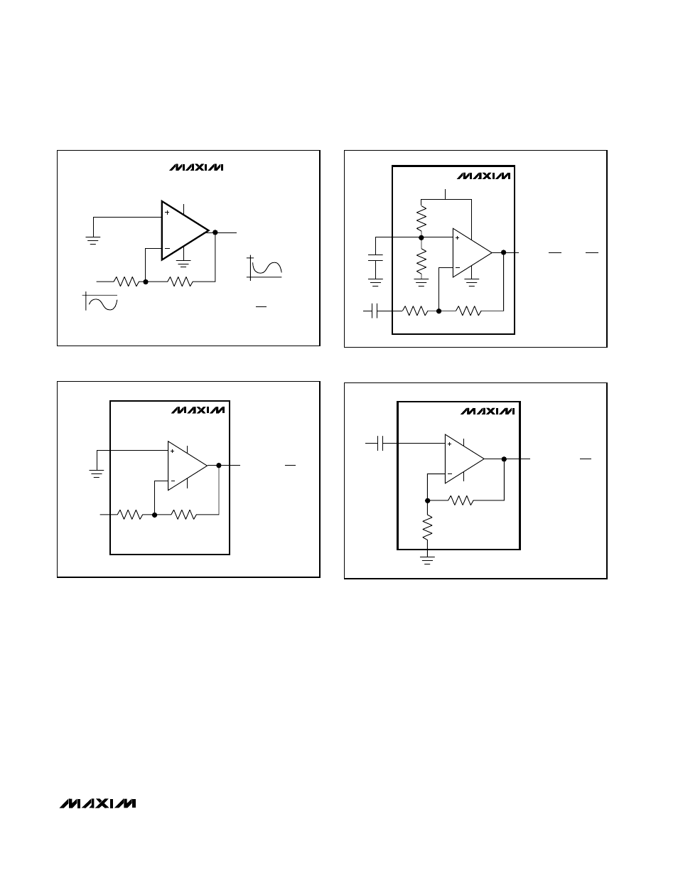
GainAmp Signal Coupling
and Configurations
Common op-amp configurations include both nonin-
verting and inverting amplifiers. Figures 5–8 show vari-
ous single and dual-supply circuit configurations.
Single-supply systems benefit from a midsupply bias
on the noninverting input (provided internally on
MAX4175/MAX4275), as this produces a quiescent DC
level at the center of the rail-to-rail output stage signal
swing. For dual-supply systems, ground-referenced
signals may be DC-coupled into the inverting or non-
inverting inputs.
IN_+ Filter on MAX4175/MAX4275
Internal resistor biasing of the V
CC
/ 2 bias options cou-
ples power-supply noise directly to the op amp’s nonin-
verting input. To minimize high-frequency power-supply
noise coupling, add a 1µF to 0.1µF capacitor from IN+
to ground to create a lowpass filter (Figure 6). The low-
pass filter resulting from the internal bias resistors and
added capacitor can help eliminate higher frequency
power-supply noise coupling through the noninverting
input.
MAX4281
V
CC
V
CC
R
G
R
F
V
IN
V
OUT
=
-R
F
(V
IN
)
R
G
Figure 4. Single-Supply, DC-Coupled Inverting Amplifier with
Negative Input Voltage
MAX4175
V
CC
R
G
R
B
R
B
R
F
V
IN
0.1
µ
F
V
OUT
=
V
CC
- V
IN
(
R
F
)
2 R
G
Figure 6. Single-Supply, AC-Coupled Inverting Amplifier
MAX4174
V
EE
V
CC
R
G
R
F
V
IN
V
OUT
= - V
IN
(
R
F
)
R
G
Figure 5. Dual-Supply, DC-Coupled Inverting Amplifier
MAX4174
V
EE
V
CC
R
G
R
F
V
IN
V
OUT
= V
IN
(
1+
R
F
)
R
G
Figure 7. Dual-Supply, AC-Coupled Noninverting Amplifier