Applications information – Rainbow Electronics MAX4284 User Manual
Page 12
MAX4174/5, MAX4274/5, MAX4281/2/4
SOT23, Rail-to-Rail, Fixed-Gain
GainAmps/Open-Loop Op Amps
12
______________________________________________________________________________________
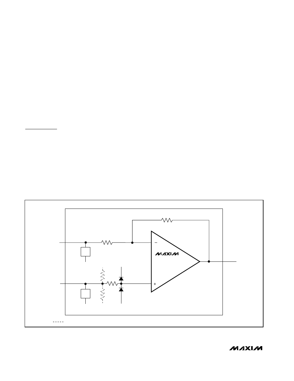
cause output phase reversal. A back-to-back SCR
structure at the input pins allows either input to safely
swing ±17V relative to V
EE
(Figure 3). Additionally, the
internal op-amp inputs are diode clamped to either
supply rail for the protection of sensitive input stage cir-
cuitry. Current through the clamp diodes is limited by a
5k
Ω
resistor at the noninverting input, and by R
G
at the
inverting input. An IN+ or IN- fault voltage as high as
±17V will cause less than 3.5mA of current to flow
through the input pin, protecting both the GainAmp and
the signal source from damage.
Applications Information
GainAmp fixed-gain amplifiers offer a precision, fixed
gain amplifier in a small package that can be used in a
variety of circuit board designs. GainAmp fixed-gain
amplifiers can be used in many op amp circuits that use
resistive negative feedback to set gain, and that do not
require other connections to the op-amp inverting input.
Both inverting and noninverting op-amp configurations
can be implemented easily using a GainAmp.
GainAmp Input Voltage Range
The MAX4174/MAX4175/MAX4274/MAX4275 combine
both an op amp and gain-setting feedback resistors on
the same chip. Because the inverting input pin is actu-
ally tied to the R
G
input series resistor, the inverting
input voltage range is different from the noninverting
input voltage range. Just as with a discrete design,
care must be taken not to saturate the inputs/output of
the core op amp, to avoid signal distortions or clipping.
The inverting inputs (IN_-) of the MAX4174/MAX4175/
MAX4274/MAX4275 must be within the supply rails or
signal distortion may result. The GainAmp’s inverting
input structure includes diodes to both supplies, such
that driving the inverting input beyond the rails may
cause signal distortions (Figure 1). For applications that
require sensing voltages beyond the rails, use the
MAX4281/MAX4282/MAX4284 open-loop op amps
(Figure 4).
OUT
IN-
IN+
R
G
R
F
5k
V
EE
V
EE
BIAS RESISTORS (MAX4175/MAX4275 ONLY)
NOTE: INPUT STAGE PROTECTION INCLUDES
TWO 17V SCRs AND TWO DIODES AT THE INPUT STAGE.
V
CC
V
CC
V
EE
MAX4174
MAX4175
MAX4274
MAX4275
17V
SCR
V
EE
17V
SCR
Figure 3. Input Protection