Figure 1. nonisolated (buck) topology – Rainbow Electronics MAX16841 User Manual
Page 9
����������������������������������������������������������������� Maxim Integrated Products 9
MAX16841
Controller IC for Dimmable Offline LED Lamps
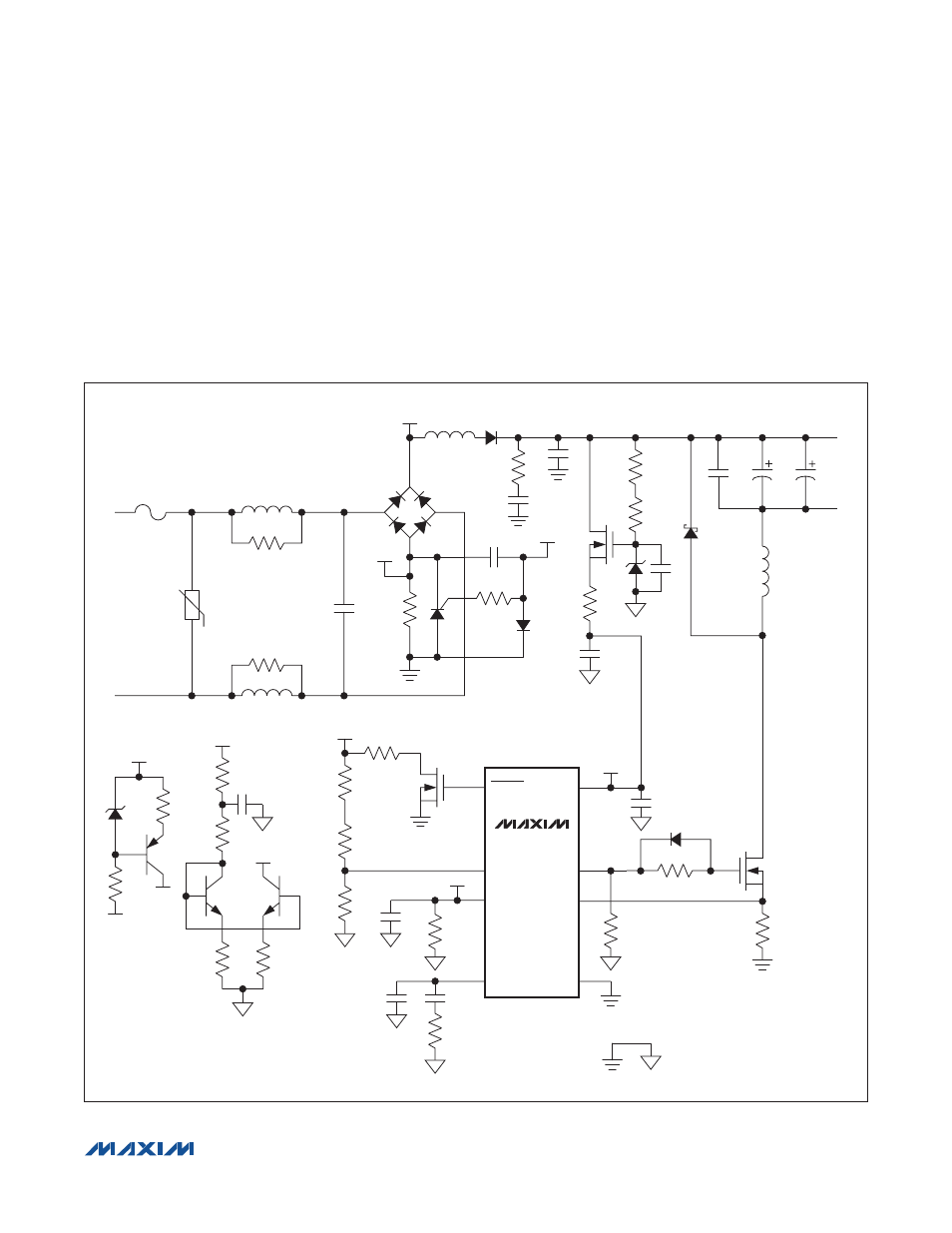
Circuit components R11, R12, C15, Q6, Q7, R13, and
R14 are used to control the input current. Q6 and Q7
are matched transistors. The voltage on C15 represents
the average input voltage. The average voltage is then
used to control the current in the current-mirror circuit
formed by R12, R13, R14, Q6, and Q7. The current
flowing into R12 is approximately proportional to the
voltage across C15 and is now reflected on the collector
of Q6, and sinks the same amount of current from the
collector of Q7 that flows into R12. Inside the device is
a 50FA current source. The current flowing into R16 sets
the input current, or the average current flowing into R20.
The circuit tries to keep the input power over the line volt-
age almost constant.
Figure 1. Nonisolated (Buck) Topology
Q2
D6
D10
15V
D3
18V
Q3
F1
L1
L3
D1
D2
1
3
DB+
4
2
R1
R2
AC2
AC1
LED+
LED-
R3
R5
R22
R23
R24
R34
C14
C13
L5
C10
C11
C12
C8
C9
D4
Q1
L2
R26
C1
C2
R20
R18
R17
R16
R10
R13
R12
R6
R4
R11
R14
Q7
Q6
Q5
R9
R7
R8
DIMOUT
TH
REFI
COMP
GND
CS
NDRV
IN
IN
8
7
6
5
2
1
REFI
REFI
3
4
U1
Q4
C5
C4
C3
C16
D12
R21
MAX16841
DB+
DB+
DB+
DB-
G
C15
G
DB-