Pin configuration, Pin description, Pin description pin configuration – Rainbow Electronics MAX16841 User Manual
Page 5
����������������������������������������������������������������� Maxim Integrated Products 5
MAX16841
Controller IC for Dimmable Offline LED Lamps
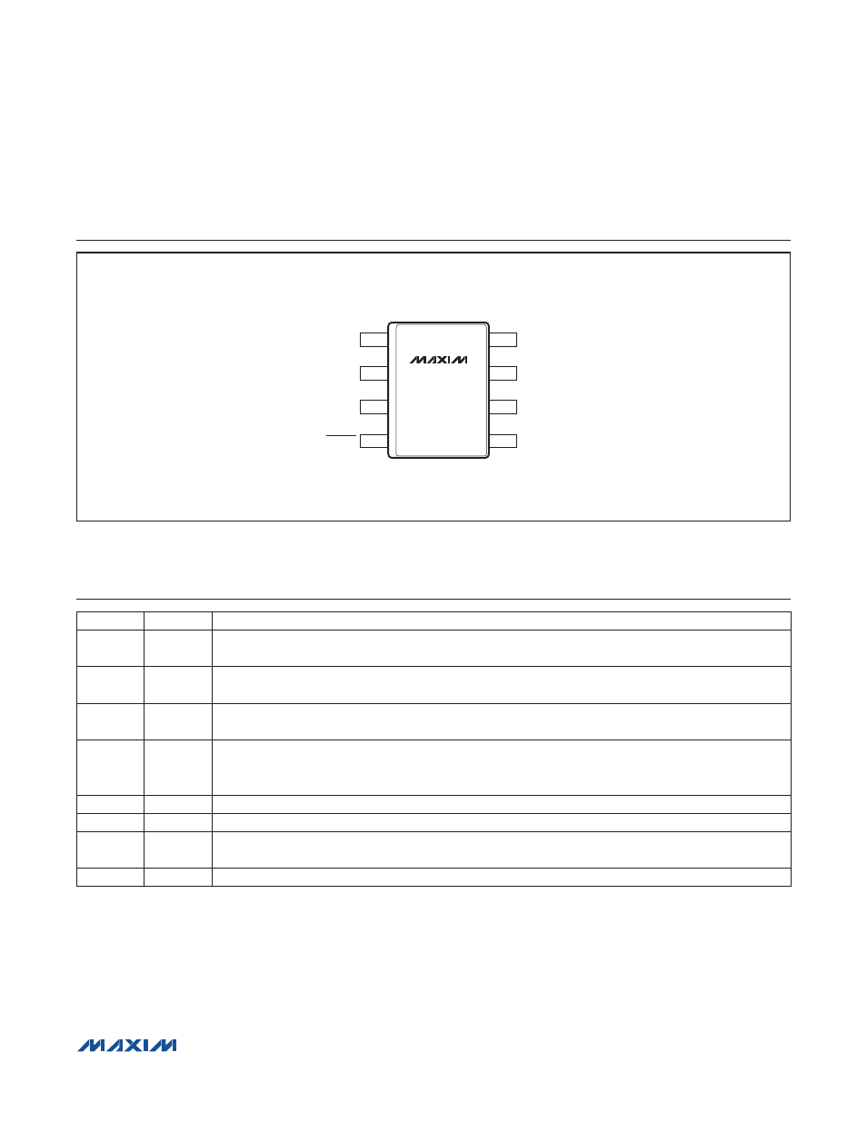
Pin Description
Pin Configuration
PIN
NAME
FUNCTION
1
REFI
Current Reference Input. The IC sources 50FA current out of this pin. Connect a resistor from REFI to
GND to set the input-current reference.
2
COMP
Compensation Component Connection for the Switching Stage. Connect a suitable RC network to
ground. This is the output of the G
m
amplifier.
3
TH
Sets the Voltage Threshold on the Input at Which Switching Starts. This threshold is set at 1.24V.
Connect a resistor-divider from the bridge rectifier output, TH, and GND.
4
DIMOUT
DIMOUT Drives an External FET to Provide a Resistive Path for the Triac when Input is Low. DIMOUT is
also used to drive an external FET that sets the programmed current to zero when the input voltage is
low.
5
GND
Ground
6
CS
Switch Current-Sense Input
7
NDRV
Gate Drive for the Switching MOSFET. Connect a resistor across NDRV and GND to set the
switching frequency.
8
IN
Input. Bypass with a 0.1FF or a higher value ceramic capacitor to ground.
REFI
+
COMP
TH
1
2
3
4
8
7
6
5
DIMOUT
IN
NDRV
CS
GND
SO
TOP VIEW
MAX16841