Digital and dc electrical characteristics, Ac electrical characteristics – Rainbow Electronics ADC1251 User Manual
Page 4
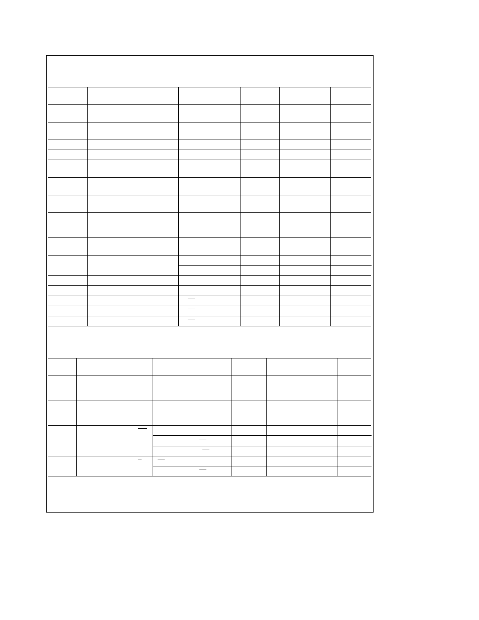
Digital and DC Electrical Characteristics
The following specifications apply for DV
CC
e
AV
CC
e a
5 0V V
b
e b
5 0V V
REF
e a
5 0V and f
CLK
e
3 5 MHz unless
otherwise specified Boldface limits apply for T
A
e
T
J
e
T
MIN
to T
MAX
all other limits T
A
e
T
J
e
25 C (Notes 6 and 7)
Symbol
Parameter
Condition
Typical
Limit
Units
(Note 9)
(Note 10 19)
(Limit)
V
IN(1)
Logical ‘‘1’’ Input Voltage for
V
CC
e
5 25V
2 0
V(min)
All Inputs except CLK IN
V
IN(0)
Logical ‘‘0’’ Input Voltage for
V
CC
e
4 75V
0 8
V(max)
All Inputs except CLK IN
I
IN(1)
Logical ‘‘1’’ Input Current
V
IN
e
5V
0 005
1
m
A(max)
I
IN(0)
Logical ‘‘0’’ Input Current
V
IN
e
0V
b
0 005
b
1
m
A(max)
V
T
a
CLK IN Positive-Going
2 8
2 7
V(min)
Threshold Voltage
V
T
b
CLK IN Negative-Going
2 1
2 3
V(max)
Threshold Voltage
V
H
CLK IN Hysteresis
0 7
0 4
V(min)
V
T
a
(min) b V
T
b
(max)
V
OUT(1)
Logical ‘‘1’’ Output Voltage
V
CC
e
4 75V
I
OUT
e b
360 mA
2 4
V(min)
I
OUT
e b
10 mA
4 5
V(min)
V
OUT(0)
Logical ‘‘0’’ Output Voltage
V
CC
e
4 75V
0 4
V(max)
I
OUT
e
1 6 mA
I
OUT
TRI-STATE Output Leakage
V
OUT
e
0V
b
0 01
b
3
m
A(max)
Current
V
OUT
e
5V
0 01
3
m
A(max)
I
SOURCE
Output Source Current
V
OUT
e
0V
b
20
b
6 0
mA(min)
I
SINK
Output Sink Current
V
OUT
e
5V
20
8 0
mA(min)
DI
CC
DV
CC
Supply Current
CS e ‘‘1’’
1
2 5
mA(max)
AI
CC
AV
CC
Supply Current
CS e ‘‘1’’
2 8
10
mA(max)
I
b
V
b
Supply Current
CS e ‘‘1’’
2 8
10
mA(max)
AC Electrical Characteristics
The following specifications apply for DV
CC
e
AV
CC
e
a
5 0V V
b
e
b
5 0V t
r
e
t
f
e
20 ns unless otherwise specified
Boldface limits apply for T
A
e
T
J
e
T
MIN
to T
MAX
all other limits T
A
e
T
J
e
25 C (Notes 6 and 7)
Symbol
Parameter
Conditions
Typical
Limit
Units
(Note 9)
(Note 10 19)
(Limit)
f
CLK
Clock Frequency
MHz
0 5
MHz(min)
6 0
3 5
MHz(max)
Clock Duty Cycle
50
%
40
%(min)
60
%(max)
t
C
Conversion Time using WR
27(1 f
CLK
)
27(1 f
CLK
) a 250 ns
(max)
to start a Conversion
f
CLK
e
3 5 MHz AZ e ‘‘1’’
7 7
7 95
m
s(max)
f
CLK
e
1 75 MHz AZ e ‘‘0’’
15 4
15 65
m
s(max)
t
C
Conversion Time using S H
AZ e ‘‘1’’
34(1 f
CLK
)
34(1 f
CLK
) a250 ns
(max)
to start a Conversion
f
CLK
e
3 5 MHz AZ e ‘‘1’’
9 7
9 95
m
s(max)
4