Rainbow Electronics MAX17075 User Manual
Page 17
MAX17075
Boost Regulator with Integrated Charge Pumps,
Switch Control, and High-Current Op Amp
______________________________________________________________________________________
17
Reference Voltage (REF)
The reference voltage is nominally 1.25V, and can
source at least 50µA (see the
Typical Operating
Characteristics
). V
CC
is the input of the internal refer-
ence block. Bypass REF with a 0.22µF ceramic capaci-
tor connected between REF and AGND.
Power-Up Sequence and Soft-Start
Once the voltage on V
CC
exceeds the XAO UVLO
threshold of approximately 1.5V, the reference turns on.
With a 0.22µF REF bypass capacitor, the reference
reaches its regulation voltage of 1.25V in approximately
1ms. When the reference voltage exceeds 1V and V
CC
exceeds its UVLO threshold of approximately 2.25V,
the IC enables the main step-up regulator, the gate-on
linear-regulator controller, and the gate-off linear-
regulator controller simultaneously.
The IC employs soft-start for each regulator to minimize
inrush current and voltage overshoot and to ensure a
well-defined startup behavior. Each output uses a 7-bit
soft-start DAC. For the step-up and the gate-on linear
regulator, the DAC output is stepped in 128 steps from
zero up to the reference voltage. For the gate-off linear
regulator, the DAC output steps from the reference
down to 250mV in 128 steps. The soft-start duration is
10ms (typ) for step-up regulator and 3ms (typ) for gate-
on and gate-off regulators.
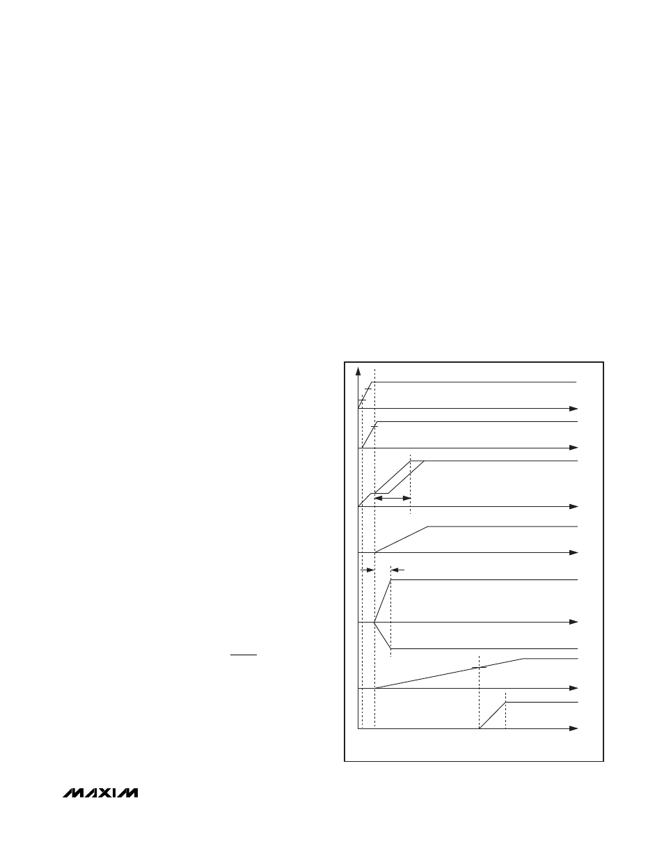
A capacitor (C
DEL
) from DEL to AGND determines the
switch-control-block startup delay. After the input volt-
age exceeds the UVLO threshold (2.25V typ) and the
soft-start routine for each regulator is complete and
there is no fault detected, a 5mA current source starts
charging C
DEL
. Once the capacitor voltage exceeds
1.25V (typ), the switch-control block is enabled as
shown in Figure 8. After the switch-control block is
enabled, COM can be connected to SRC or DRN
through the internal p-channel switches, depending
upon the state of CTL. Before startup and when V
IN
is
less than UVLO, DEL is internally connected to AGND
to discharge C
DEL
. Select C
DEL
to set the delay time
using the following equation:
Undervoltage Lockout (UVLO)
The UVLO circuit compares the input voltage at V
CC
with the UVLO threshold (2.25V rising, 2.20V falling, typ)
to ensure the input voltage is high enough for reliable
operation. The 50mV (typ) hysteresis prevents supply
transients from causing a restart. Once the input voltage
exceeds the UVLO rising threshold, startup begins.
When the input voltage falls below the UVLO falling
threshold, the controller turns off the main step-up regu-
lator and disables the switch-control block; the opera-
tional amplifier output is high impedance.
Fault Protection
During steady-state operation, if the output of the main
regulator or any of the linear-regulator outputs exceed
their respective fault-detection thresholds, the
MAX17075 activates an internal fault timer. If any condi-
tion or combination of conditions indicates a continuous
fault for the fault-timer duration (50ms typ), the
MAX17075 sets the fault latch to shut down all the out-
puts except the reference. Once the fault condition is
removed, cycle the input voltage (below the UVLO
falling threshold) to clear the fault latch and reactivate
the device. The fault-detection circuit is disabled during
the soft-start time.
C
DELAY TIME
µA
V
DEL
=
×
_
.
5
1 25
Figure 8. Power-Up Sequence
1.5V
1V
1.25V
INPUT
VOLTAGE
OK
SWITCH
CONTROL
ENABLED
14ms
3ms
SOFT-START
SOFT-START
SOFT-START BEGINS
2.25V
VVCC
VREF
VAVDD
VCOM
VPOUT
VGOFF
VDEL
VGON