Detailed description – Rainbow Electronics MAX17075 User Manual
Page 12
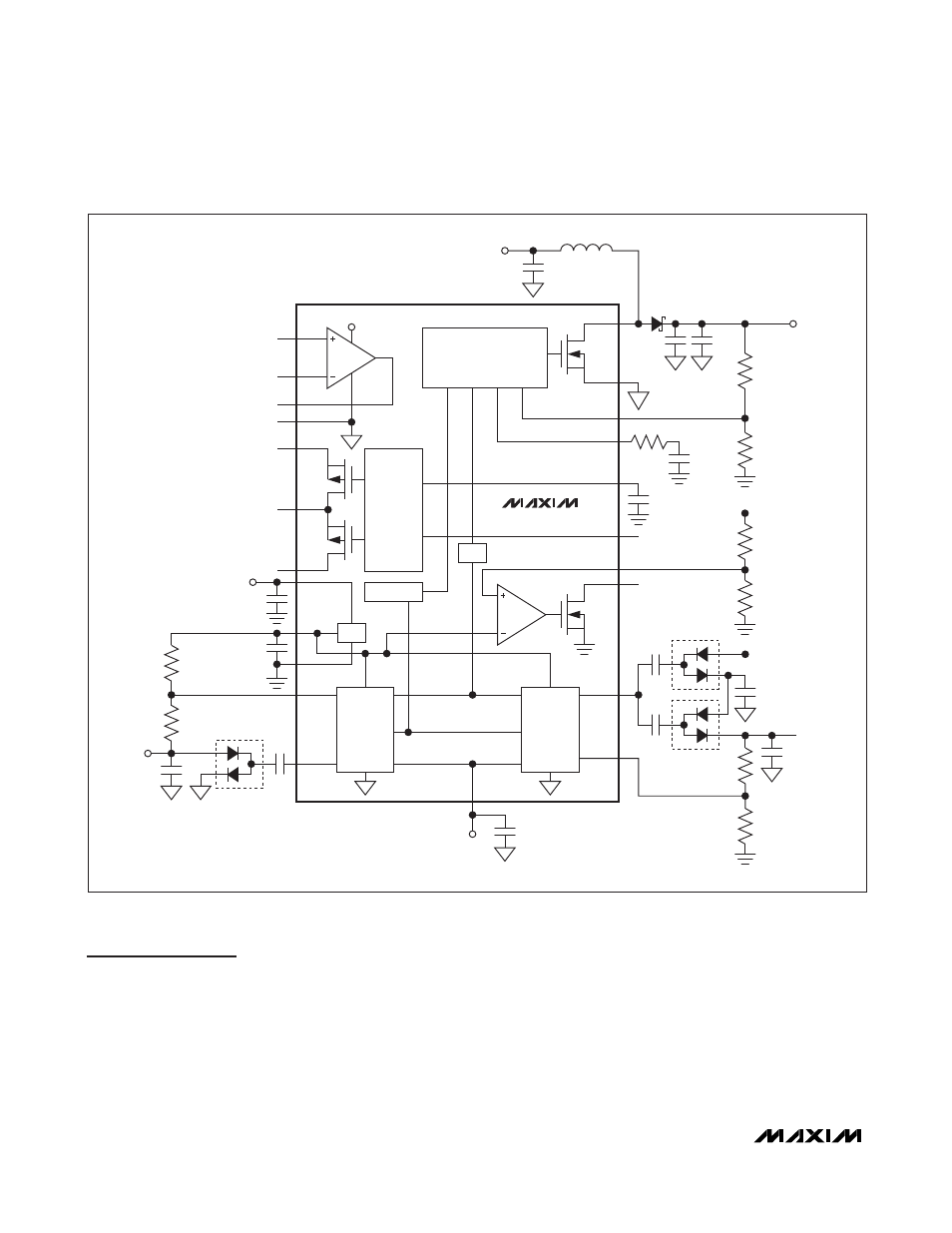
Detailed Description
The MAX17075 contains a step-up switching regulator
to generate the source driver supply, and two charge-
pump regulators to generate the gate-driver supplies.
Each regulator features adjustable output voltage, digi-
tal soft-start, and timer-delayed fault protection. The
step-up regulator uses fixed-frequency current-mode
control architecture. The MAX17075 also includes one
high-performance operational amplifier designed to
drive the LCD backplane (VCOM). The amplifier fea-
tures high output current, fast slew rate (45V/µs), wide
bandwidth (20MHz), and rail-to-rail outputs. In addition,
the MAX17075 features a high-voltage switch-control
block, a 1.25V reference output, well-defined power-up
and power-down sequences, and thermal-overload
protection. Figure 2 shows the MAX17075 functional
block diagram.
MAX17075
Boost Regulator with Integrated Charge Pumps,
Switch Control, and High-Current Op Amp
12
______________________________________________________________________________________
MAX17075
POS
LX
PGND
FB
OUT
BGND
FBN
DRVN
COM
REF
V
GON
V
VCC
DRN
VCC
AGND
SRC
SUP
NEG
SWITCH
CONTROL
SEQUENCE
BOOST
CONTROLLER
NEGATIVE
CHARGE
PUMP
POSITIVE
CHARGE
PUMP
REF
OSC
RSTIN
COMP
V
VCC
V
GOFF
DEL
DRVP
FBP
SUP
CTL
RST
FROM TCON
V
AVDD
V
VCC
V
AVDD
POUT
V
AVDD
Figure 2. Functional Diagram