Typical operating circuit – Rainbow Electronics MAX17075 User Manual
Page 11
MAX17075
Boost Regulator with Integrated Charge Pumps,
Switch Control, and High-Current Op Amp
______________________________________________________________________________________
11
MAX17075
AGND
VCC
BGND
DRVN
REF
FBN
POS
NEG
OUT
LX
PGND
RSTIN
FB
COMP
DRN
RST
COM
SRC
DRVP
FBP
SUP
CTL
DEL
C11
0.1
μF
R14
1k
Ω
R10
100k
Ω
R6
13.7k
Ω
R7
100k
Ω
R3
100k
Ω
R1
10
Ω
R12
20k
Ω
R15
464k
Ω
R11
R13
10k
Ω
R8
187k
Ω
R9
20k
Ω
C12
220pF
C10
1
μF
C9
0.22
μF
C5
1
μF
C13
0.01
μF
R16
20k
Ω
V
AVDD
TO V
COM
D4
V
IN
2.5V TO 5.5V
(4.5 TO 5.5V FOR FULL LOAD)
V
AVDD
13V/500mA
V
GON
30V/20mA
V
GOFF
-7V/20mA
C15
0.1
μF
D2
C17
0.1
μF
D3
C1
10
μF
6.3V
C2
10
μF
6.3V
C14
1
μF
C6
1
μF
C16
1
μF
C3
10
μF
25V
C4
10
μF
25V
L1
3.0
μH
D1
FROM SYSTEM
3.3V
V
IN
V
AVDD
V
AVDD
V
AVDD
FROM TCON
C8
0.033
μF
EP
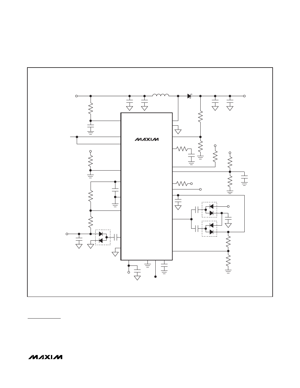
Figure 1. Typical Operating Circuit
Typical Operating Circuit
The typical operating circuit (Figure 1) of the
MAX17075 is a complete power-supply system for TFT
LCD panels in monitors and TVs. The circuit generates
a +13V source driver supply, a +30V positive gate-dri-
ver supply, and a -7V negative gate-driver supply from
a +2.5V to +5.5V input supply. Table 1 lists some
selected components, and Table 2 lists the contact
information for component suppliers.