Selector guide chip information – Rainbow Electronics MAX5097 User Manual
Page 17
MAX5096/MAX5097
40V, 600mA Buck Converters with Low-
Quiescent-Current Linear Regulator Mode
______________________________________________________________________________________
17
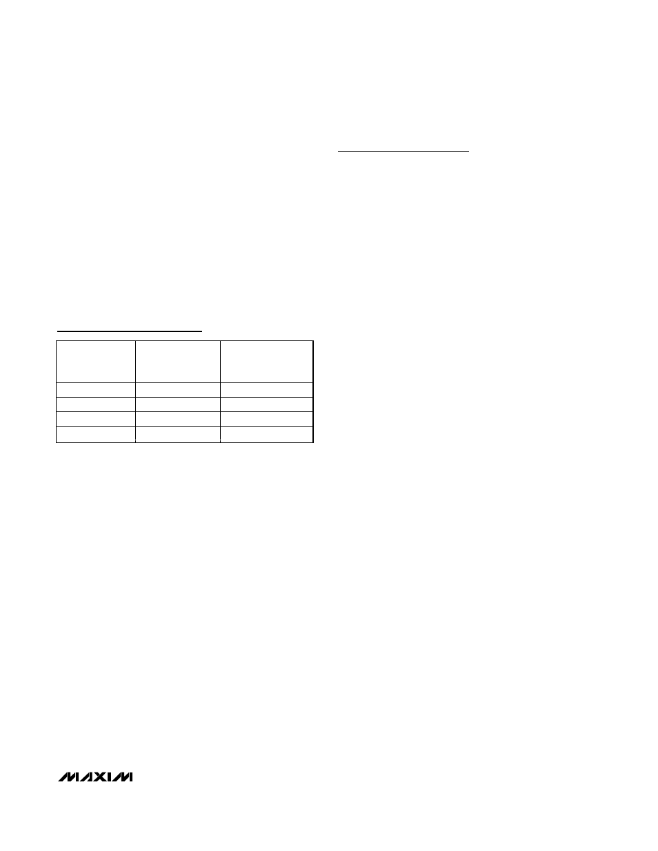
PART
OUTPUT
VOLTAGE
(V)
SWITCHING
FREQUENCY
(kHz)
MAX5096A_ _ _
+3.3/Adjustable
135
MAX5096B_ _ _
+5.0/Adjustable
135
MAX5097A_ _ _
+3.3/Adjustable
330
MAX5097B_ _ _
+5.0/Adjustable
330
Selector Guide
Chip Information
PROCESS: BiCMOS
3) Connect the exposed pad of the IC to the SGND
plane. Do not make a direct connection between the
exposed pad plane and SGND (pin 2) under the IC.
Connect the exposed pad and pin 2 to the SGND
plane separately. Connect the ground connection of
the feedback resistive divider, the soft-start capaci-
tor, the adjustable reset timeout capacitor, and the
compensation network to the SGND plane. Connect
the SGND plane and PGND plane at one point near
the input bypass capacitor at V
IN
.
4) Use the large SGND plane as a heatsink for the
MAX5096/MAX5097. Use large PGND and LX
planes as heatsinks for the rectifier diode and the
inductor.