Reset – Rainbow Electronics MAX5097 User Manual
Page 12
MAX5096/MAX5097
Output Voltage Tracking/Sequencing
The output voltages of multiple MAX5096/MAX5097
converters can be made to track by using the SS pin
during turn-on and turn-off (see Figure 3). SS is pulled
up using a 5µA current source and connecting SS of
multiple MAX5096/MAX5097s, raising the references
with the same slope. Tracking the converters reduces
the differential voltages between the core and I/O volt-
ages during turn-on, turn-off, and brownout. If any one
converter output drops due to shutdown or an overload
fault situation, the SS drops, pulling down all the con-
verters simultaneously. The rate of fall of output volt-
ages, however, depends on the output capacitance
and load of the individual converter.
Multiple voltage sequencing can be done by daisy-
chaining several MAX5096/MAX5097s. The RESET of
the first converter can be connected to EN of the sec-
ond converter. This allows the first converter to come
up first every time the system is powered up.
Power-On Reset Output (
RESET
)
A supervisor circuit is integrated in the MAX5096/
MAX5097. RESET is an open-drain output. RESET pulls
low as soon as V
OUT
drops below 90% of its nominal
regulation voltage. Once the output voltage rises above
92% of the set output voltage, the RESET output enters
a high-impedance state after the active timeout period
(t
RP
). The active timeout period is externally program-
mable using a single capacitor from CT to ground. Use
the following equation to calculate the required timeout
period for the power-on reset:
where V
CT-TH
is 1.237V, I
CH
is 1µA, t
RP
is in seconds,
and C
CT
is in Farads.
To obtain a logic-voltage output, connect a pullup
resistor from RESET to a logic-supply voltage. The
internal open-drain MOSFET can sink 1mA while provid-
ing a TTL logic-low signal. If unused, ground RESET or
leave it unconnected.
The power-on reset behavior is the same in both the
LDO and Buck Modes of operation.
Oscillator/Synchronization Input (SYNC)
The MAX5096/MAX5097 internal oscillator generates a
factory-preset frequency of either 135kHz (MAX5096)
or 330kHz (MAX5097). The 135kHz version keeps the
maximum fundamental frequency below 150kHz, which
keeps the third harmonic below 450kHz and under the
t
V
I
C
RP
CT TH
CH
CT
=
×
−
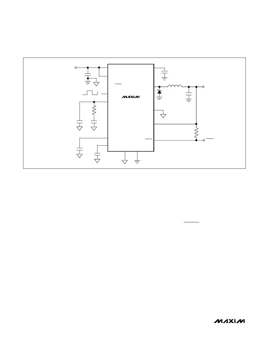
40V, 600mA Buck Converters with Low-
Quiescent-Current Linear Regulator Mode
12
______________________________________________________________________________________
PGND
OUT
LX
V
IN
GND
BP
V
IN
V
OUT
ADJ
22
µH
C
OUT
22
µF
(CER.)
COMP
SYNC
D1*
B260/
MURS105
C
IN
100
µF
LDO/BUCK
RESET
EN
CT
SS
C
P
22pF
C
SS
0.047
µF
C
CT
0.01
µF
100k
Ω
+
1.0
µF
MAX5096
MAX5097
R
C
100k
Ω
C
C
1.2nF
*USE MURS105 IN APPLICATIONS
WHERE LDO MODE QUIESCENT
CURRENT IS CRITICAL.
RESET
Figure 2. Fixed Output Voltage Configuration